English
 français
 Deutsch
 español
 italiano
 português


Peugeot 205 GTI 1.9 - Box 13

Kit 49
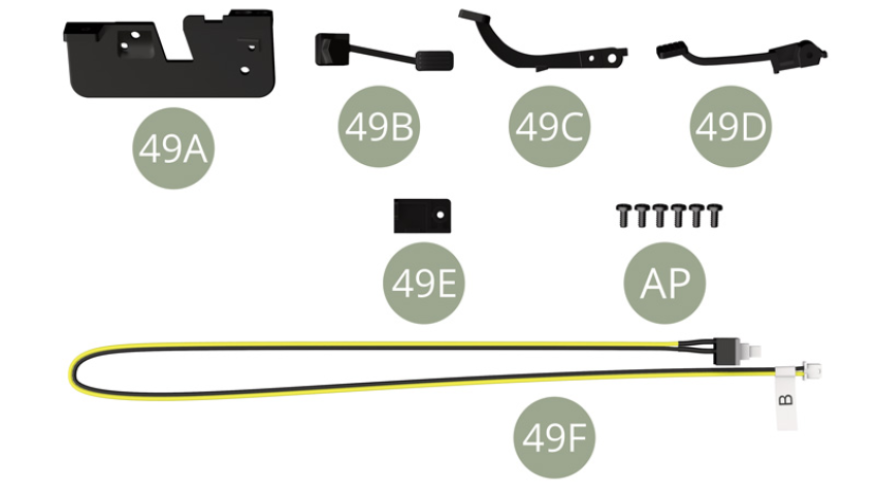
Parts of kit
- 49A Pedals’ panel
- 49B Accelerator pedal
- 49C Brake pedal
- 49D Clutch pedal
- 49E Switch holder
- 49F Brake switch cable
- AP M 1,7 x 4 mm (x 6)
Step 1
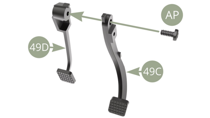
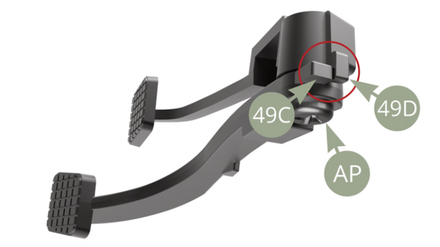
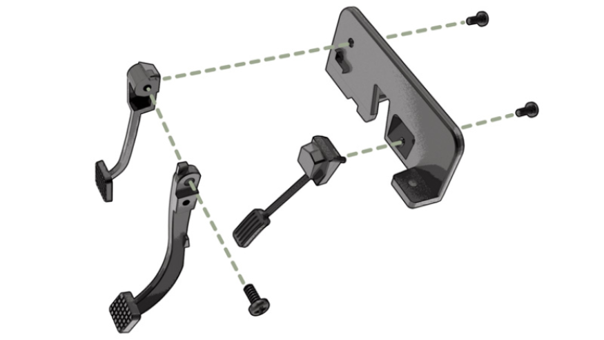
Fit 49C Brake pedal to 49D Clutch pedal and fix with AP screw ( don’t overtighten , allow pedals movement ) . Note mutual orientation of 49D Clutch and 49C Brake pedals as shown below in red circle
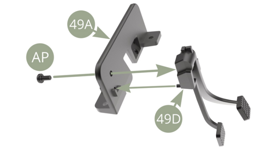
Fit 49D Clutch pedal to 49A Pedals’ panel and fix with AP screw.
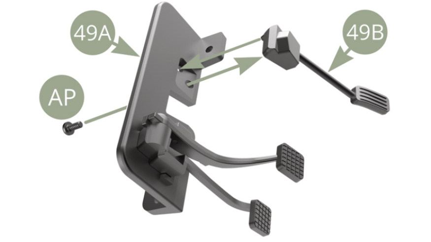
Fit 49B Accelerator pedal to 49A Pedals’ panel and fix with AP screw.
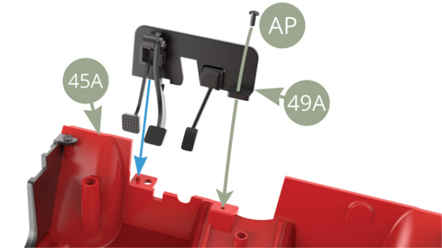
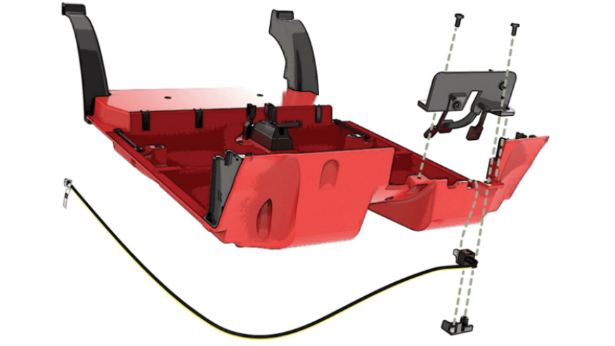
Fit 49A Pedal’s panel to 45A Cabin floor pin ( blue arrow ) and fix with AP screw.
Fit 49F Brake switch into the opening pointed by blue arrow , secure it from below by 49E Switch holder and fix the latter with AP screw to 45A Cabin floor bracket and 49A Pedals’ panel bracket.
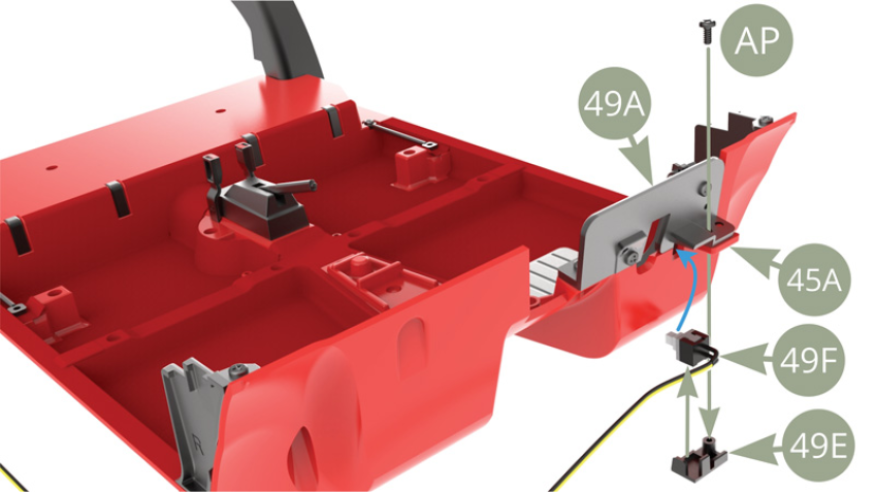
49F Brake switch installed between 49A Pedals’ panel bracket and 49E Switch holder.

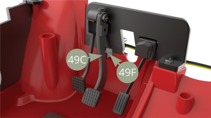
Note the achieved result of 49C Brake pedal knob aligned against 49F Brake switch.
Assembly drawings
General view
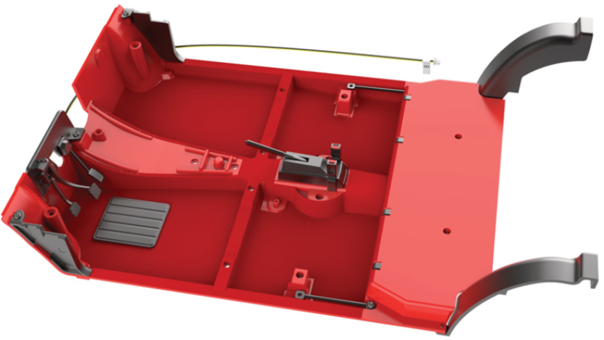
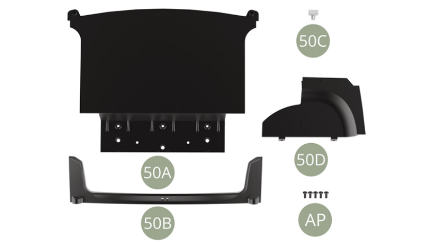
Kit 50
Parts of kit
- 50A Trunk floor
- 50B Trunk rear panel
- 50C Trunk lock
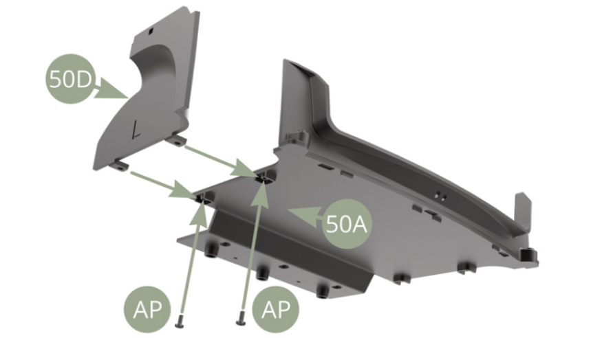
- 50D Trunk left panel
- AP M 1,7 x 4 mm (x 5)
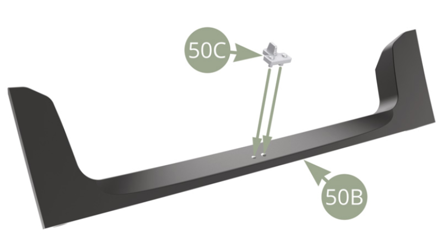
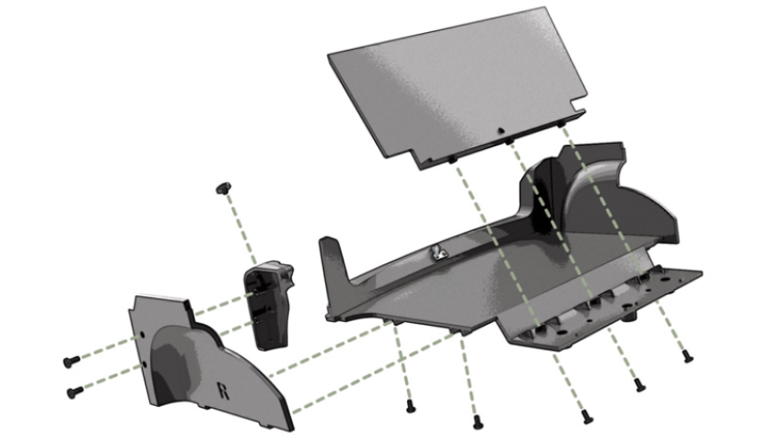
Step 2
Fit 50C Trunk lock on its two pins to 50B Trunk rear panel.
Fit 50B Trunk rear panel to 50A Trunk floor and fix with two AP screws.
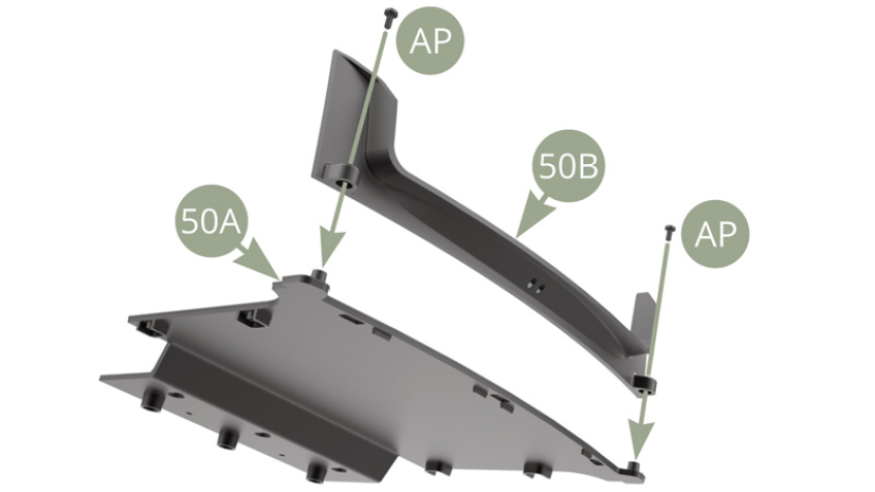
Fit 50D Trunk left panel to 50A Trunk floor and fix with two AP screws.
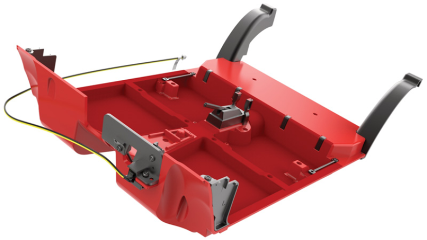
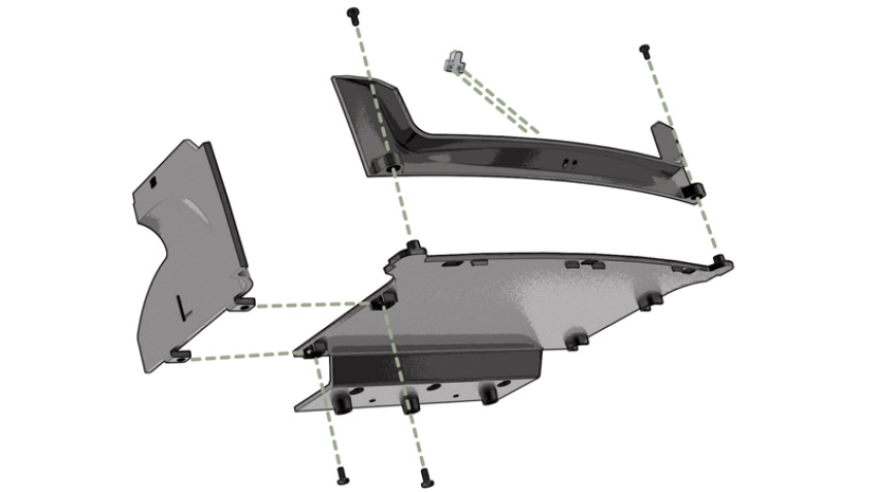
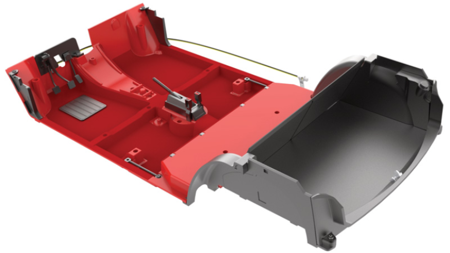
Assembly drawings
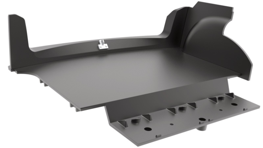
General view
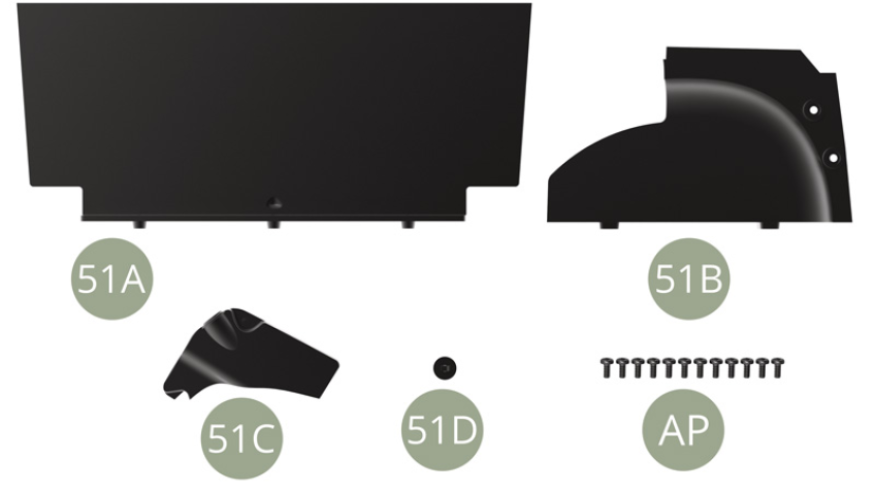
Kit 51
Parts of kit
- 51A Rear seat backrest panel
- 51B Trunk right panel
- 51C Rear screen wash fluid reservoir
- 51D Cap
- AP M 1,7 x 4 mm (x 12)
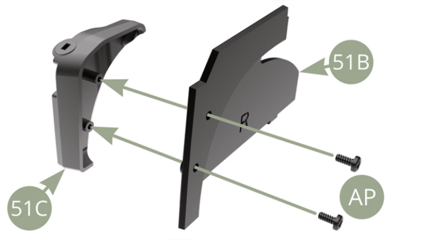
Step 3
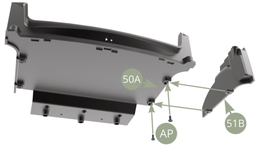
Fit 51C Rear screen wash fluid reservoir to 51B Trunk right panel and fix with two AP screws.
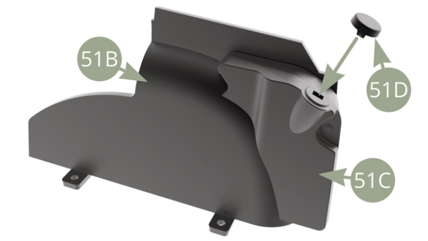
Fit 51D Cap to 51C Rear screen wash fluid reservoir.
Fit 51B Trunk right panel to 50A Trunk floor right edge and fix with two AP screws.
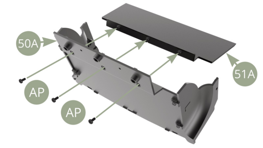
Fit 51A Rear seat backrest panel to 50A Trunk floor and fix with three AP screws.
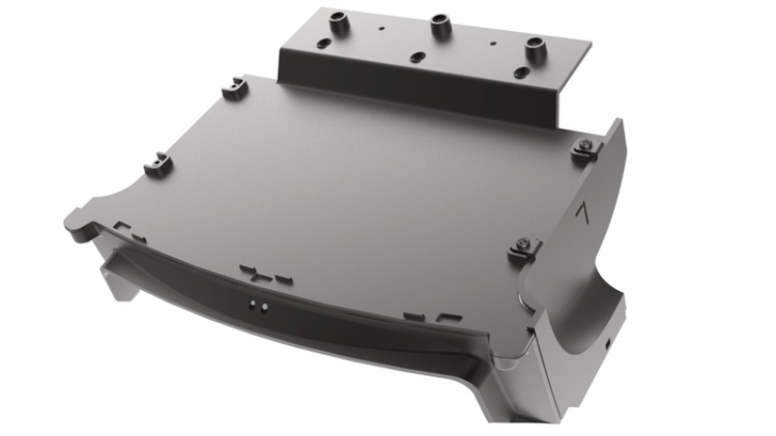
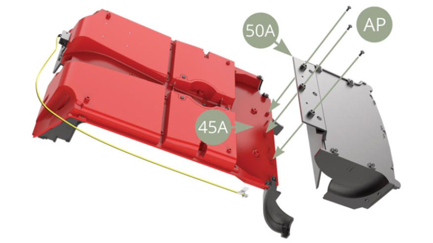
Fit 50A Trunk floor assembly to 45A Cabin floor rear edge and fix with three AP screws.
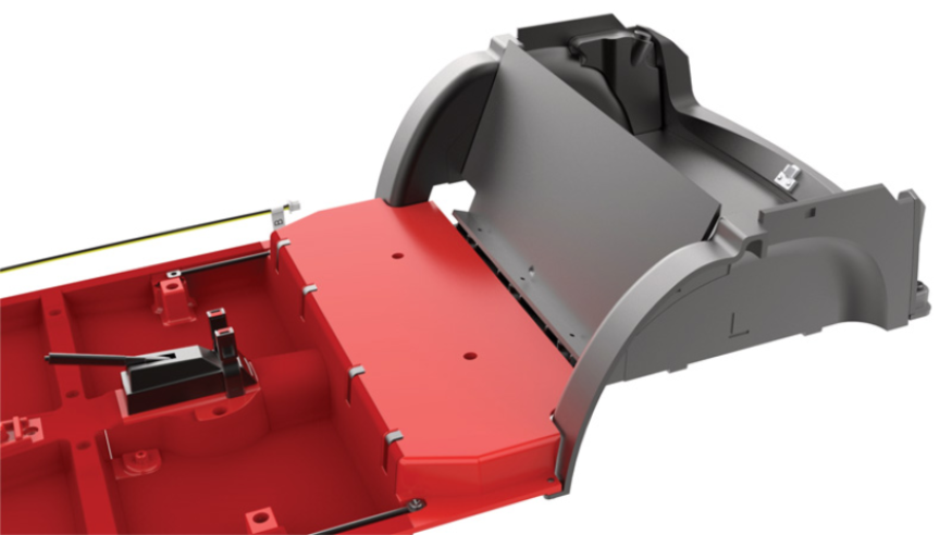
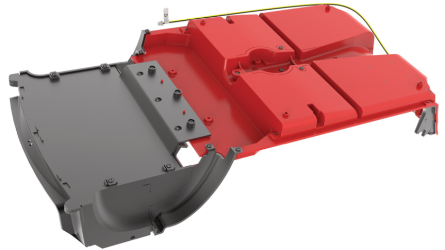
Assembly drawings

General view
Kit 52
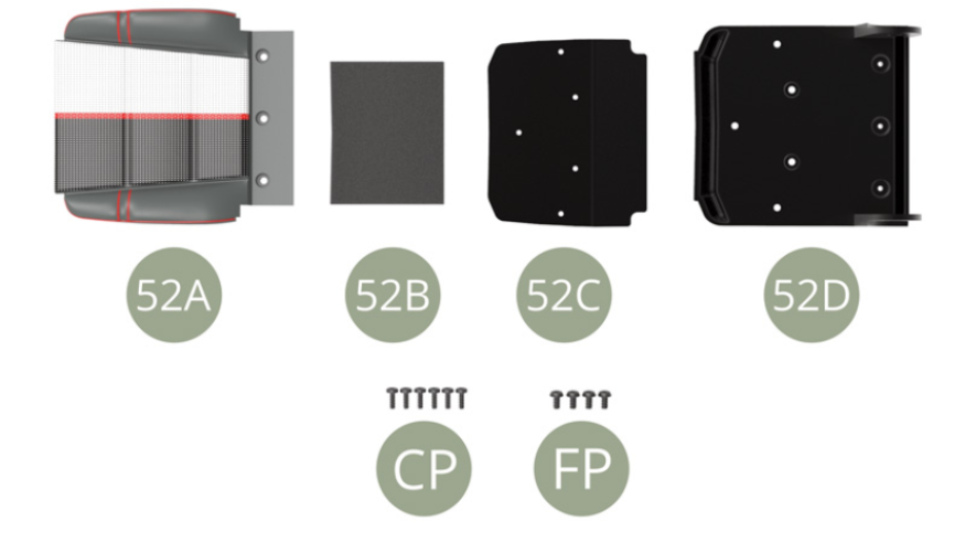
Parts of kit
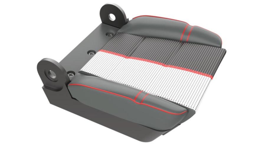
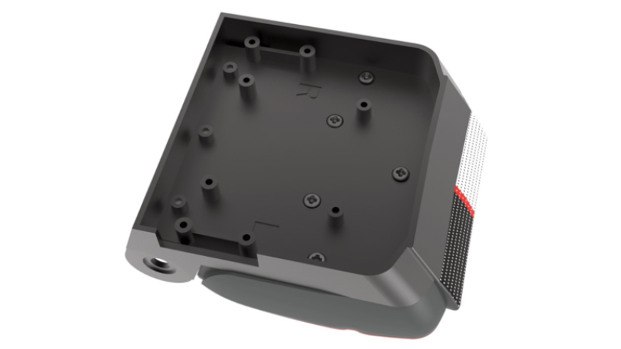
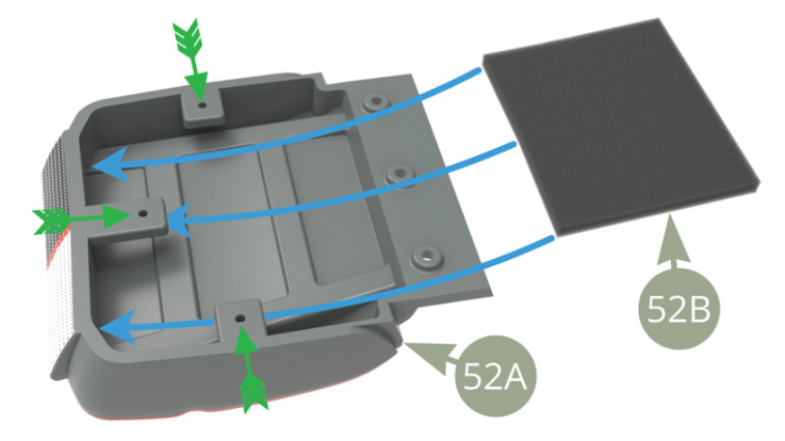
- 52A Front left seat cushion
- 52B Cushion padding
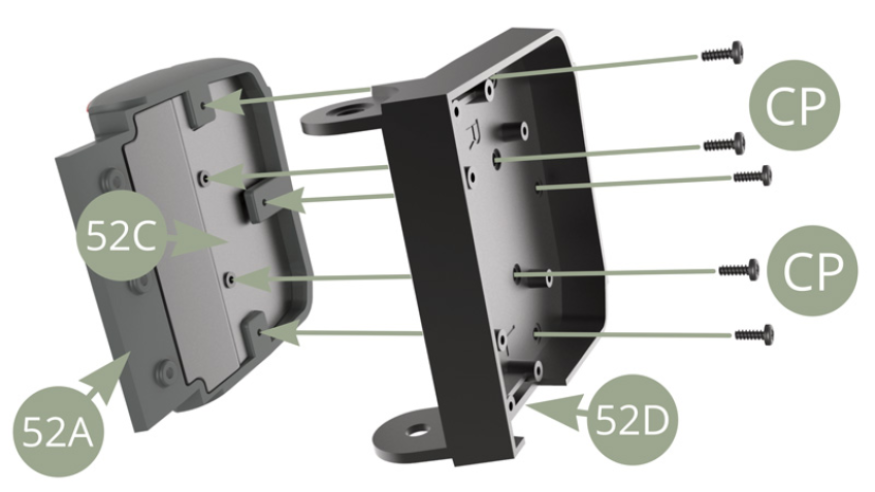
- 52C Cushion panel
- 52D Front left seat base
- CP M 1,7 x 5 mm (x 6)
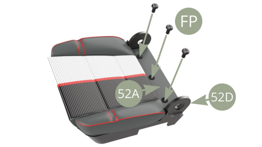
- FP M 2,0 x 4 x 4 mm (x 4)
Step 4
Slide 52B Cushion padding foam into 52A Front left seat cushion under three tabs pointed by green arrows.
Slide 52C Cushion panel into 52A Front left seat cushion , on top of 52B Cushion padding and under three tabs pointed by green arrows.

Fit 52D Front left seat base to 52A Front left seat cushion with 52C Cushion panel , and fix to the latter with five CP screws.
Fix 52A Front left seat cushion to 52D Front left seat base with three FP screws.
Assembly drawings
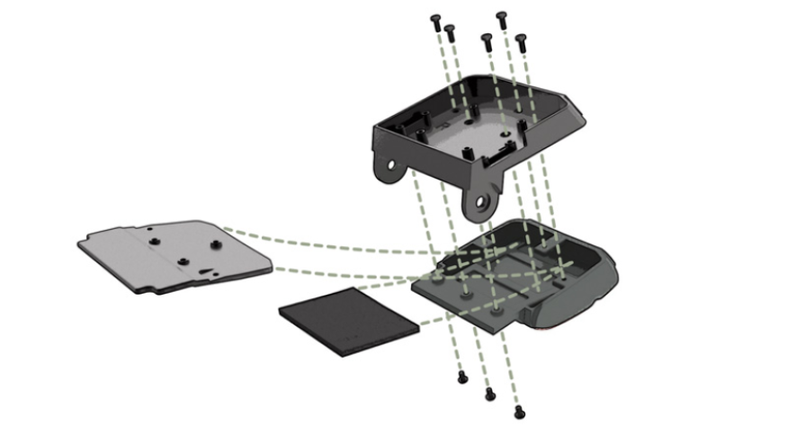
General view