English
 français
 Deutsch
 español
 italiano
 português


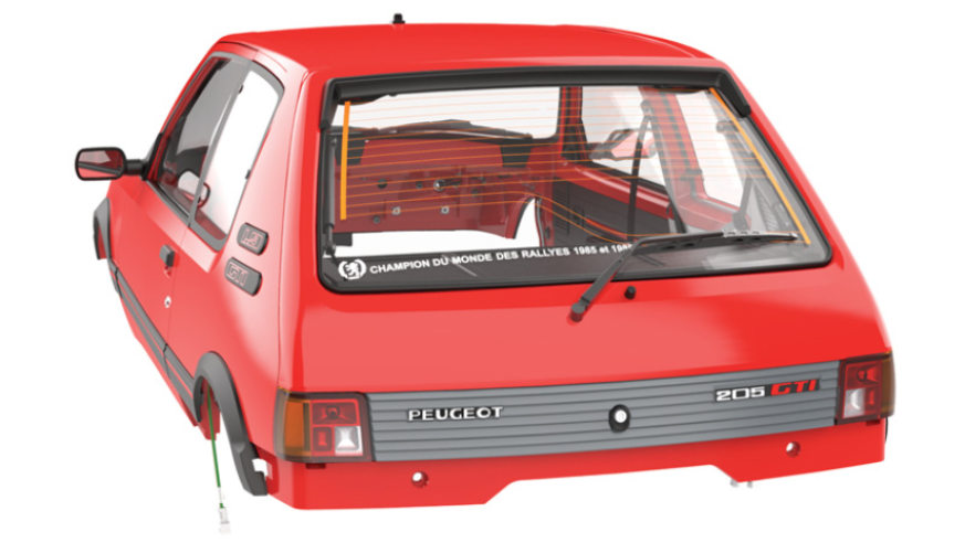
Peugeot 205 GTI 1.9 - Box 24
Kit 93
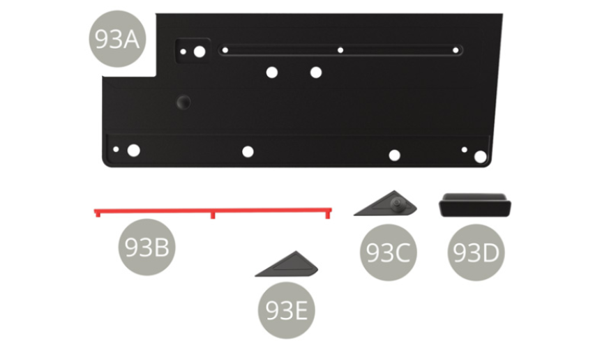
Parts of kit
- 93A Inner deco panel
- 93B Deco panel trim
- 93C Rear view mirror control panel
- 93D Elbow rest handle
- 93E Cover

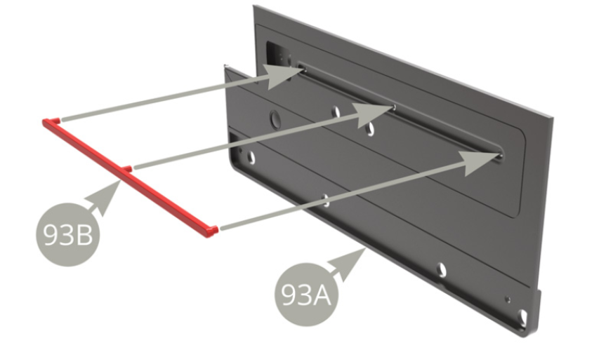
Step 1
Fit 93B Deco panel trim to 93A Inner deco panel .
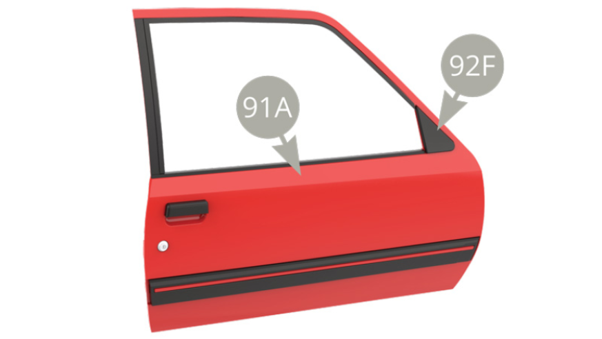
Fit 93C Rear view mirror control panel to 91A Right door .

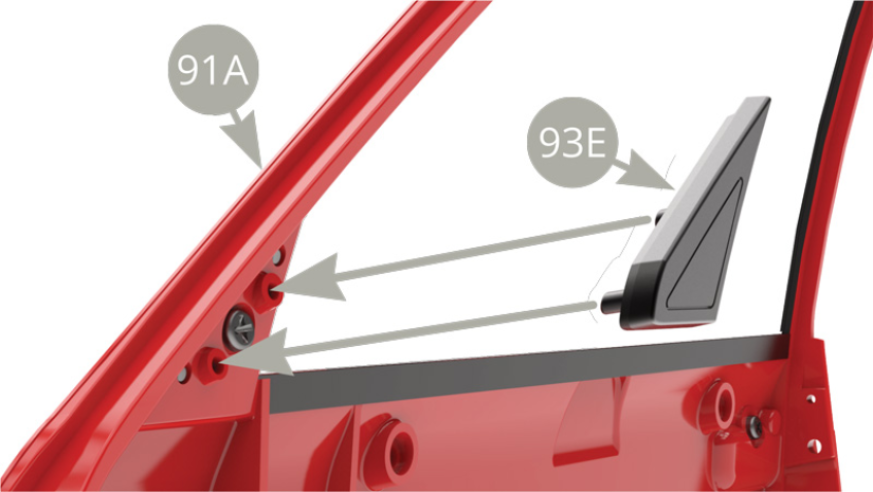
Please note , that if you have chosen to have Right door without Rear view mirror ( illustration above ) , you have to fit 93E Cover to 91A Right door ( illustration below ) .
Assembly drawings

General view
Kit 94
Parts of kit

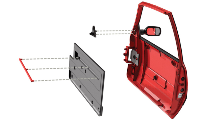
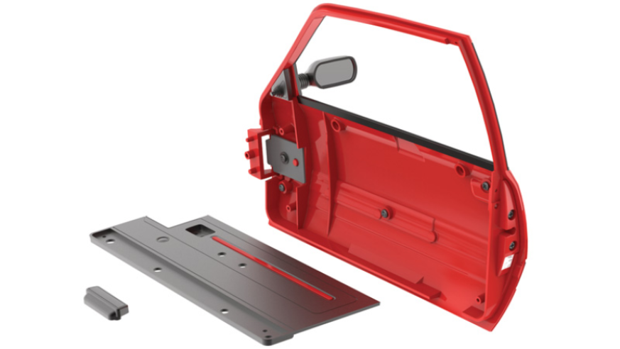
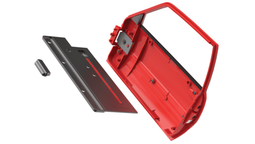
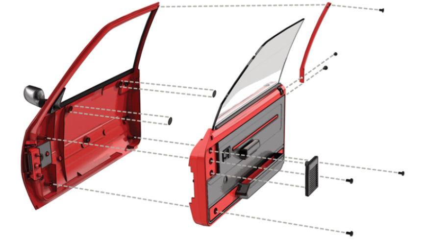
Step 2
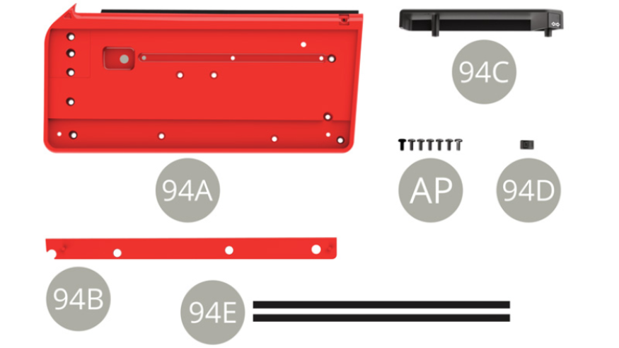
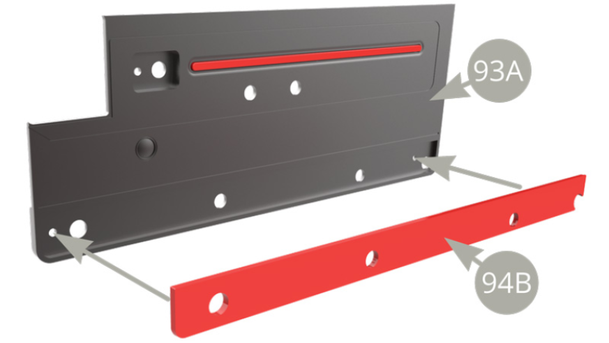
Fit 94B Deco plank to 93A Inner deco panel.
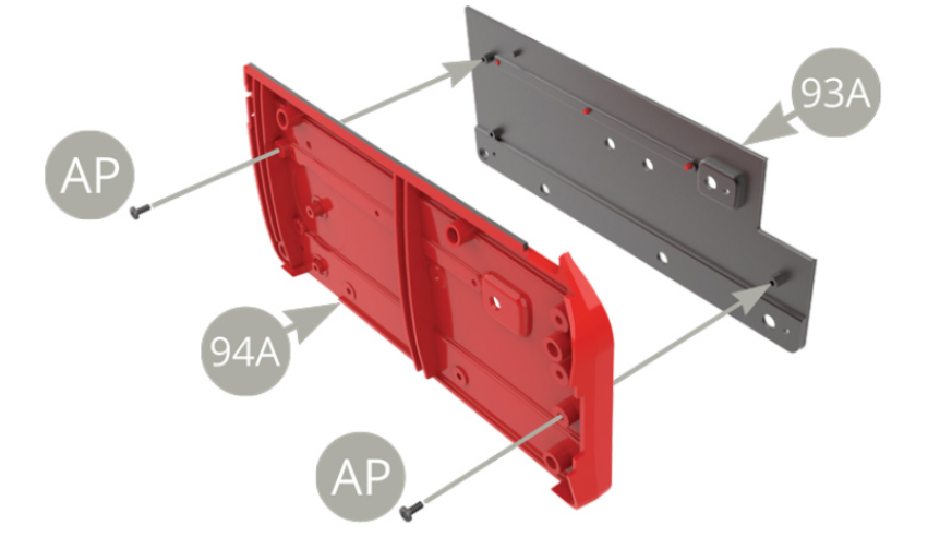
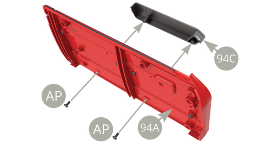
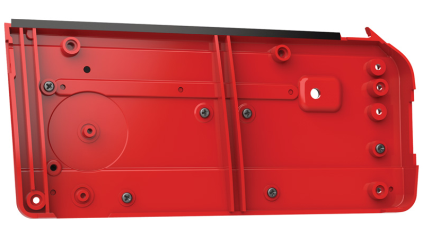
Fit 93A Inner deco panel to 94A Right door inner panel and fix with two AP screws
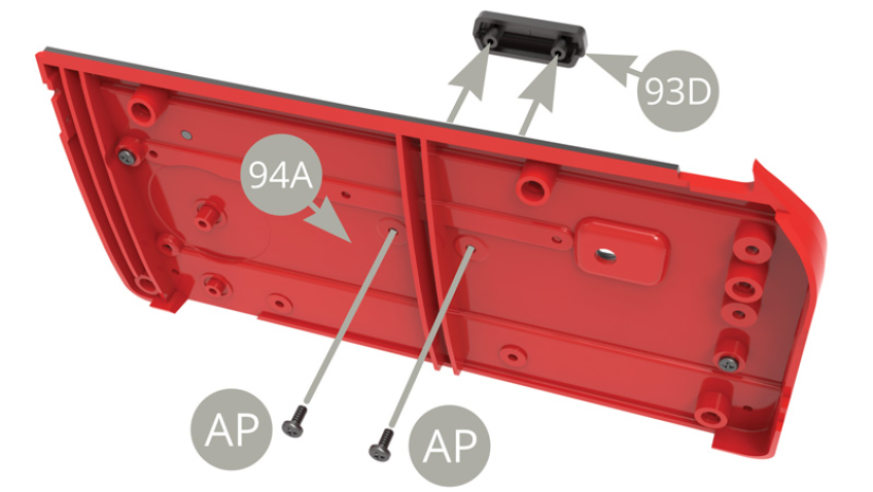
Fit 93D Elbow rest handle to 93A Inner deco panel and fix from back side to 94A Right door inner panel with two AP screws ( upper and lower illustrations ) .
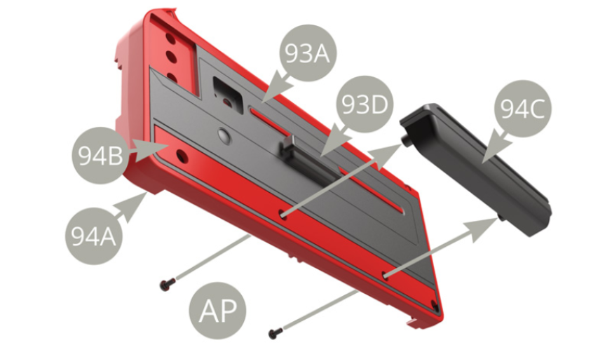
Fit 94C Door pocket to 94B Deco plank and fix to 94A Right door inner panel with two AP screws ( upper and next illustration )

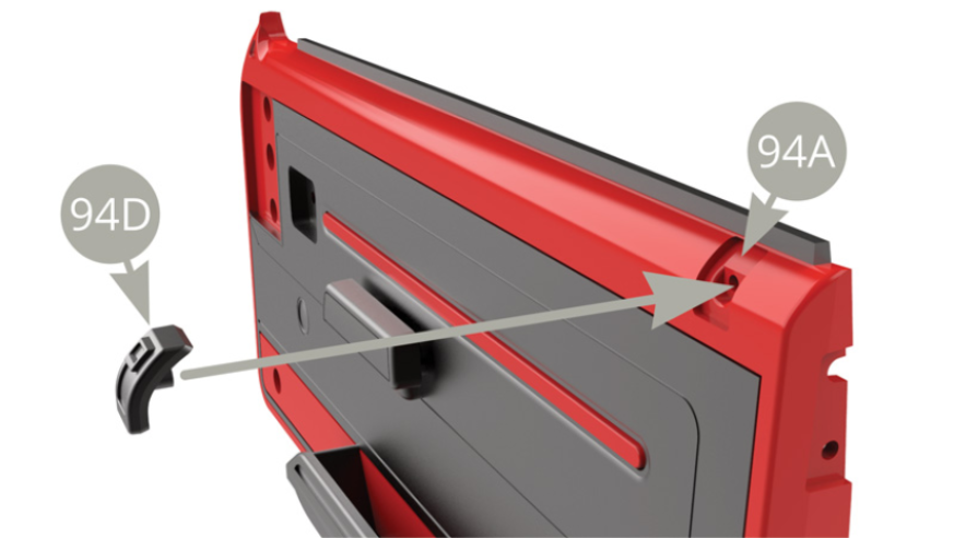
Fit 94D Locking button to 94A Right door inner panel .
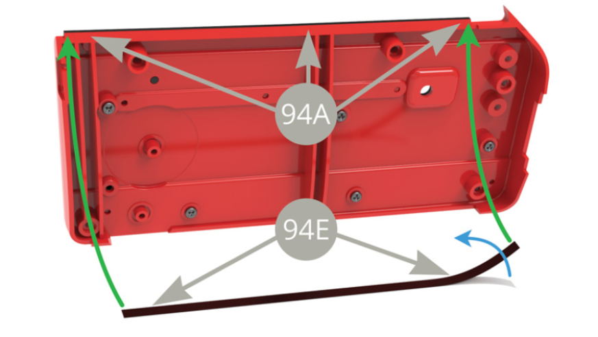
Peel 94E Glass protective strip off its backing paper ( blue arrow ) and stick along the upper edge of 94A Right door inner panel back side ( green arrows ) .
Assembly drawings
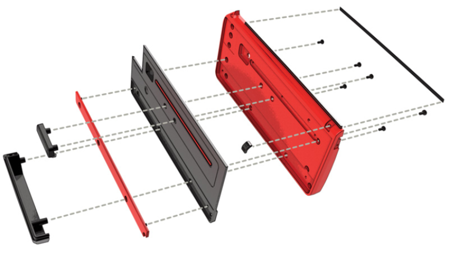
General view
Kit 95
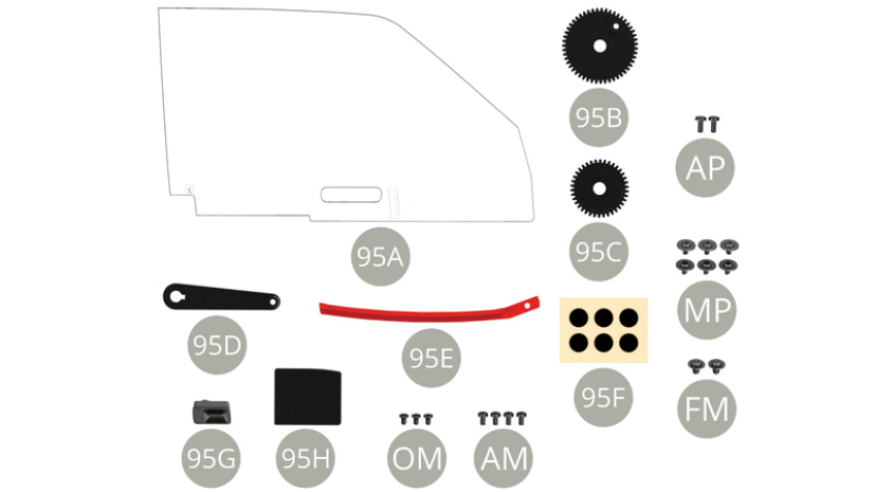
Parts of kit

Step 3
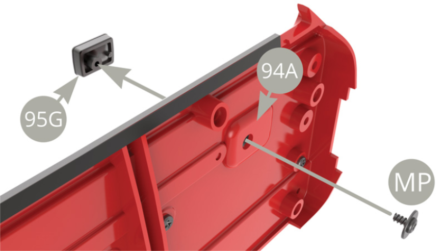
Fit 95G Unlocking lever housing to 93A Inner deco panel and fix to 94A Right door inner panel with MP screw . ( upper and lower illustrations )
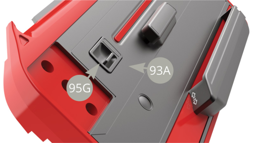

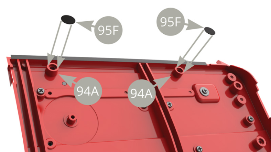
Peel two 95F Protective roundels off backing paper and stick to 94A Right door inner panel protrusions , to keep door glass from scratching during its movement
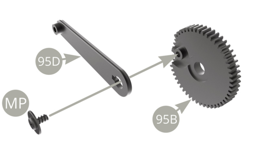
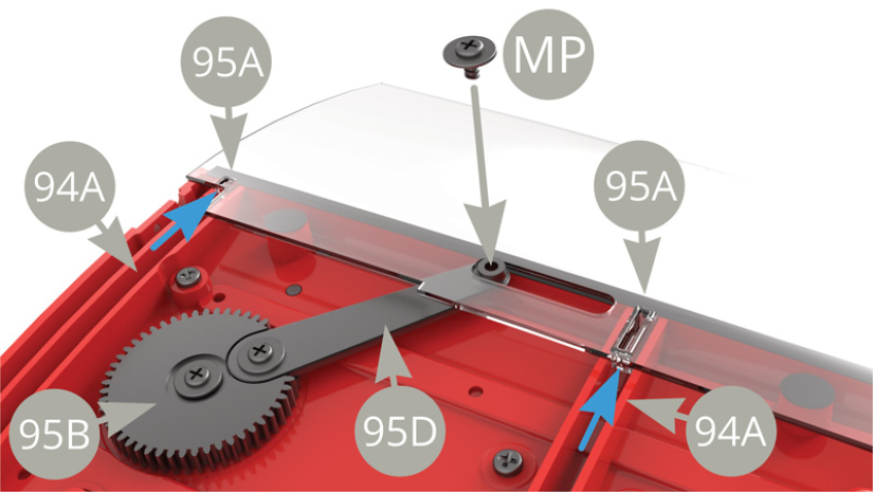
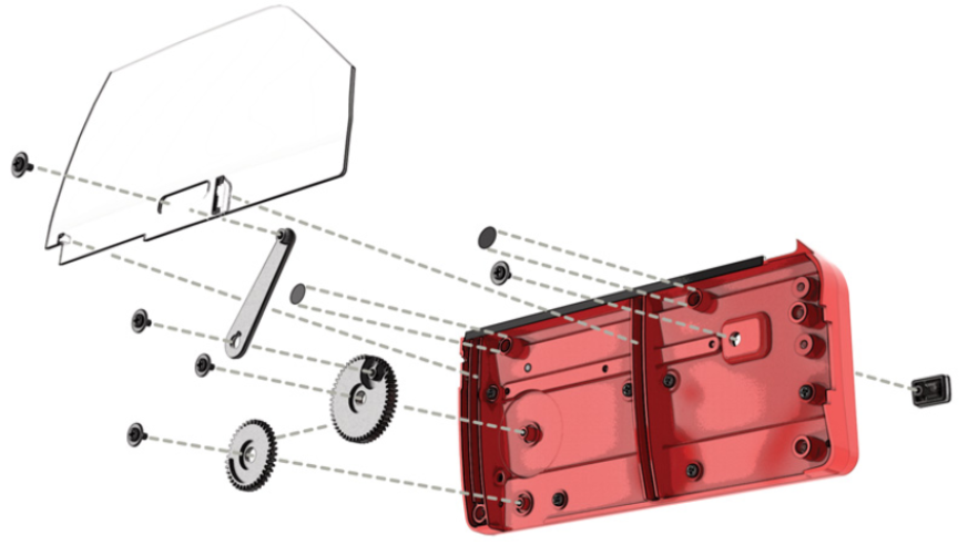
Fit 95D Lever to 95B Big gear and fix with MP screw
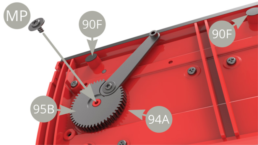
Fit 95B Big gear to 94A Right door inner panel and fix with MP screw .
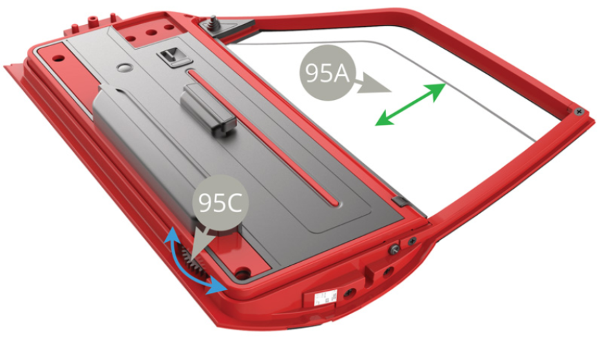
Fit 95A Right door glass with its two guiding tabs to the uppermost position ( blue arrows ) into the grooves of 94A Right door inner panel , and fix it to raised 95D Lever with MP screw .
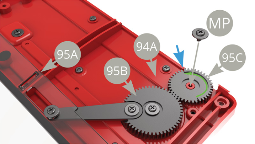
Fit 95C Small gear to 94A Right door inner panel peg ,engaging ( meshing ) it with 95B Big gear ( 95A Glass raised up ) . -Make sure to adjust the raised sector edge ( green arrow ) to be in front of blue arrow pointed edge , and then fix 95C Small gear to 94A Right door inner panel with MP screw .
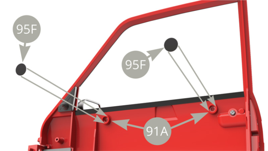
Peel two 95F Protective roundels off backing paper and stick to 91A Right door protrusions on its inner side .
Fit 94A Right door inner panel to 91A Right door and fix with three AM screws .

Fit 95E Plank to 91A Right door and fix with OM screw .
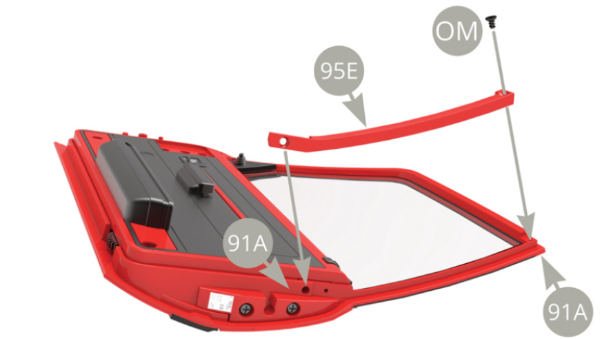
Fix 91A Right door to 94A Right door inner panel with AP screw . Fix the other end of 95E Plank to 91A Right door with OM screw

Rotate 95C Small gear ( blue arrow ) with your finger to check lowering and raising 95A Right door glass ( green arrow ).
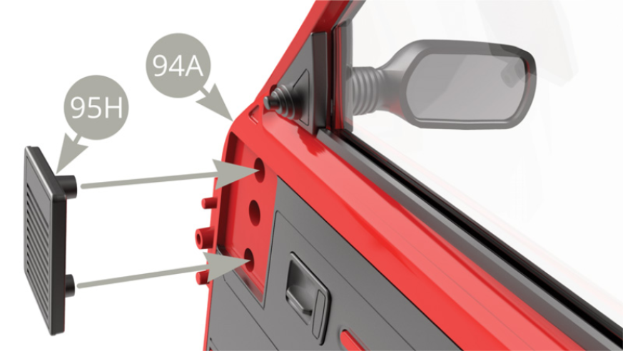
Fit 95H Radio speaker to 94A Right door inner panel
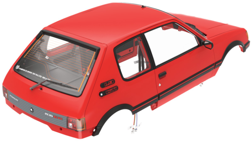
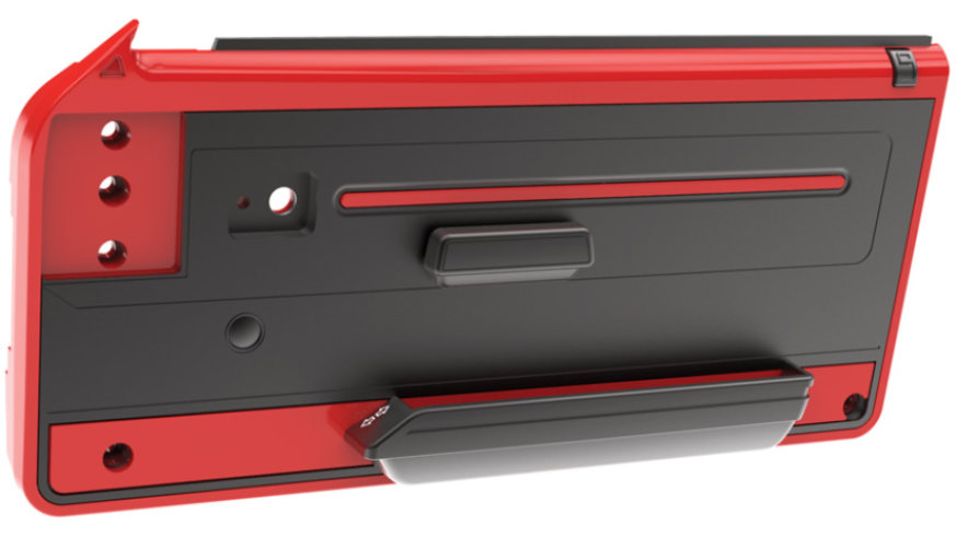
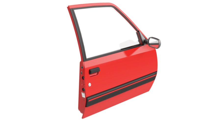
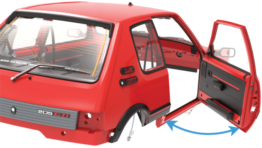
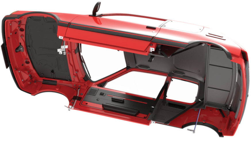
Preassembled Right door
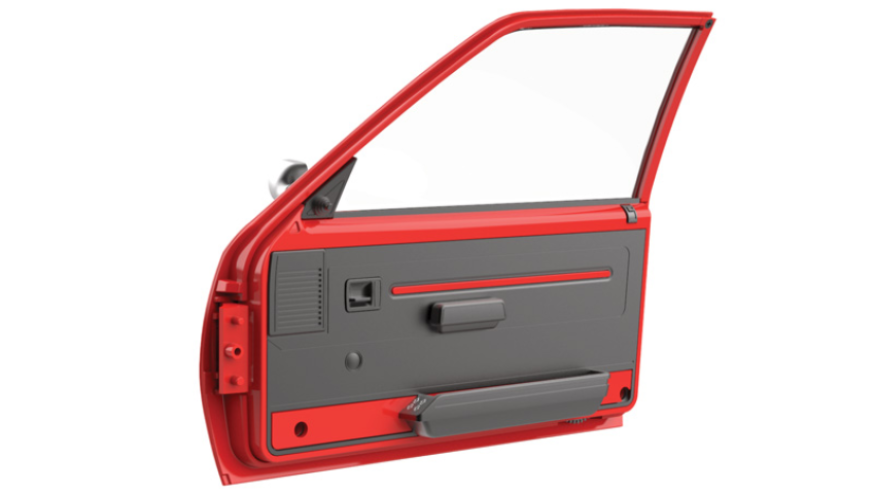
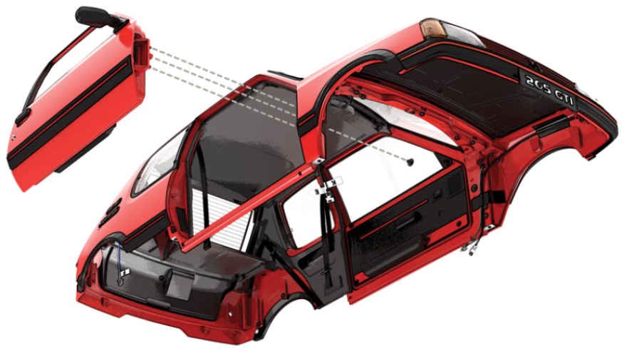
Next step is the attachment of Right door to the Bodywork
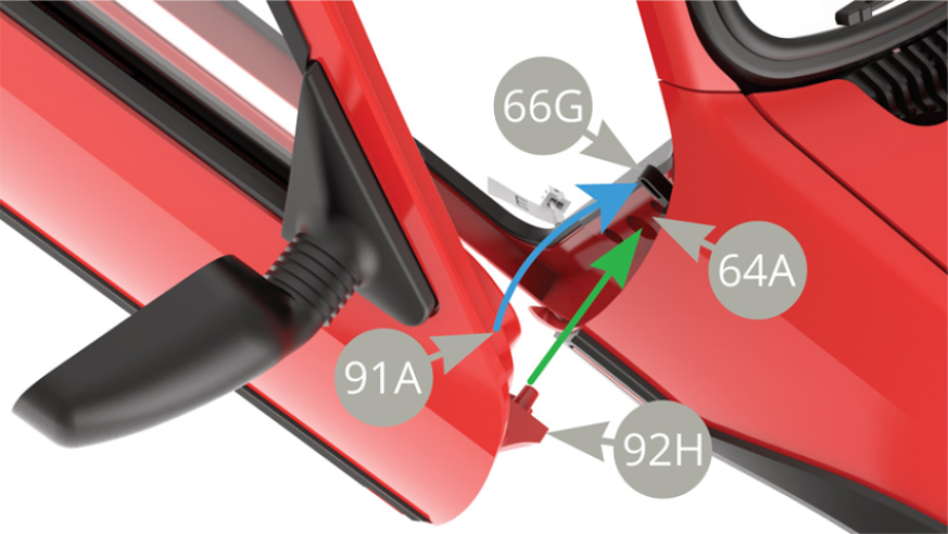
Fitting the Right door to the Bodywork , aim 92H Hinge pins to fit into the sockets on 64A Body frame ( green arrow ) , and 91A Right door inner upper corner to push up 66G Switch lever ( blue arrow ) . Refer to upper and lower illustrations .


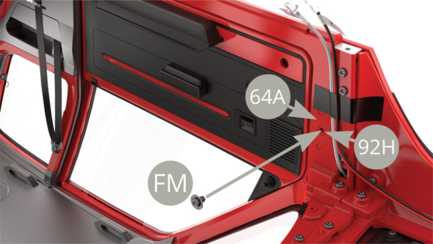
Fix 92H Hinge to 64A Body frame with FM screw .
With Right door fitted to the Bodywork , check its opening and closing function .
Assembly drawings

General view

Kit 96
Parts of kit
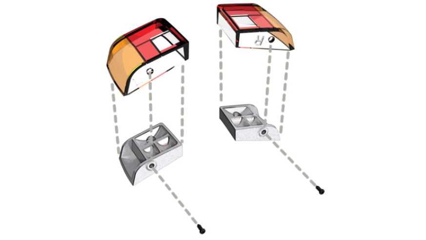
Step 4
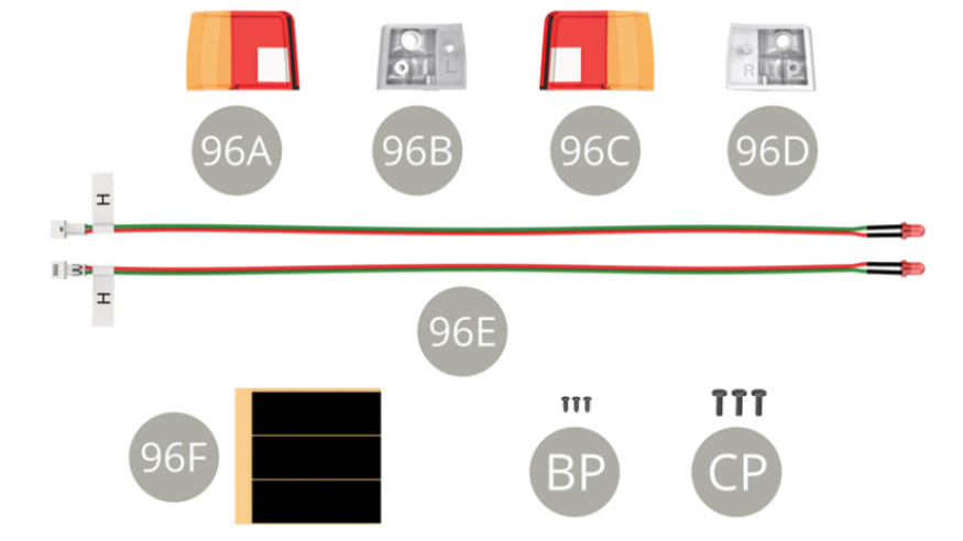
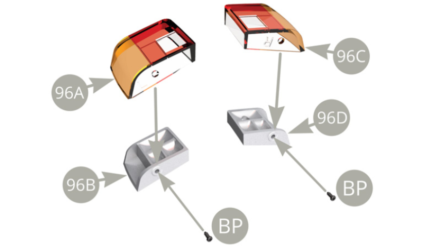
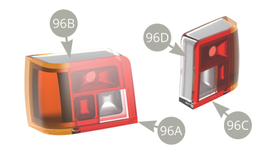
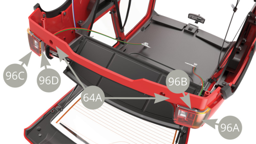
Fit 96A Left rear light cluster lens to 96B Left rear light cluster reflector and fix with BP screw . Fit 96C Right rear light cluster lens to 96D Right rear light cluster reflector and fix with BP screw .

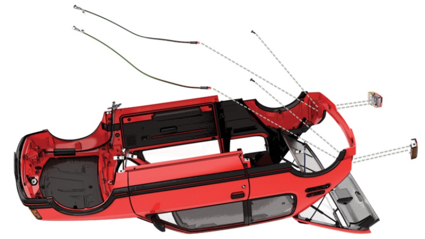
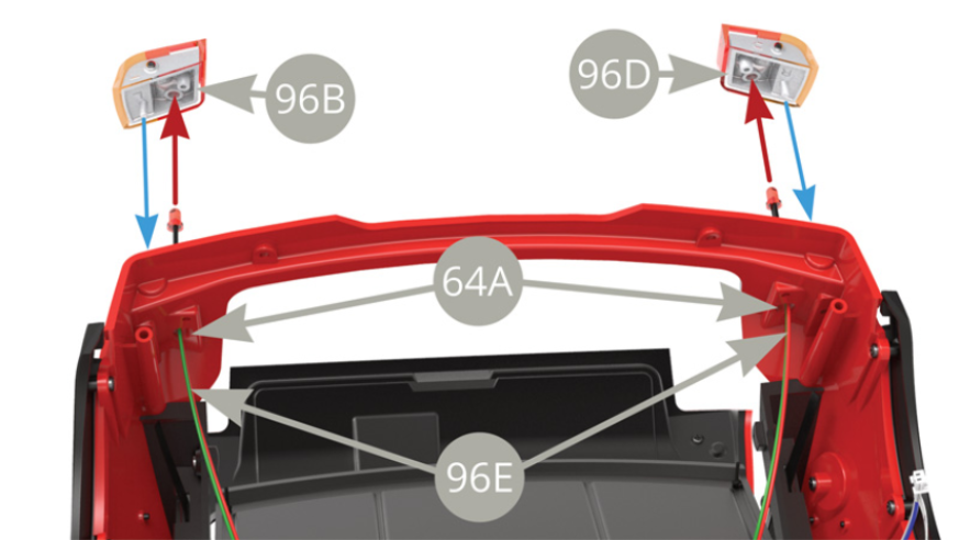
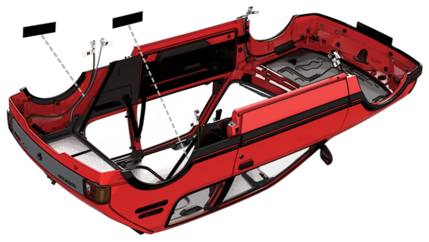
Pass two 96E H cables rear light LEDs through the openings in 64A Bodywork rear panel corners . Fit each 96E H cable LED into 96B Left and 96D Right rear light cluster reflector sockets ( red arrows ) . With LEDs installed , fit 96B Left and 96D Right rear light cluster reflectors to 64A Bodywork rear panel outer side ( blue arrows ) , follow to next illustration .
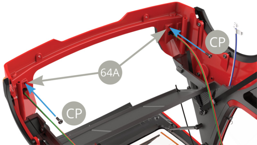
With 96A/96B Left and 96C/96D Right rear lights now fitted to 64A Bodywork panel , secure each one to it with two CP screws ( lower illustration blue arrows ) .

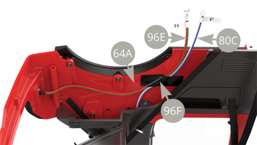
Lead right side 96E H cable along 64A Bodywork side and together with 80C F cable fix by 96F Tape piece .
Lead left side 96E H cable along 64A Bodywork side and fix by 96F Tape piece .
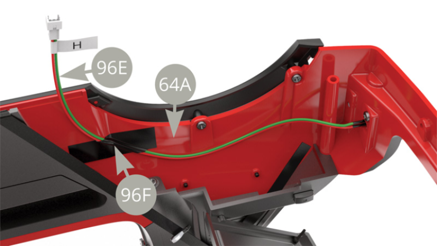
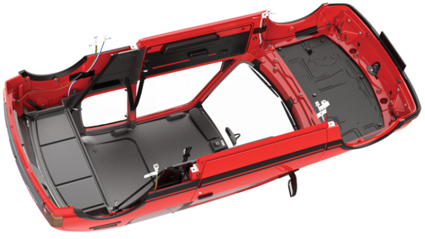
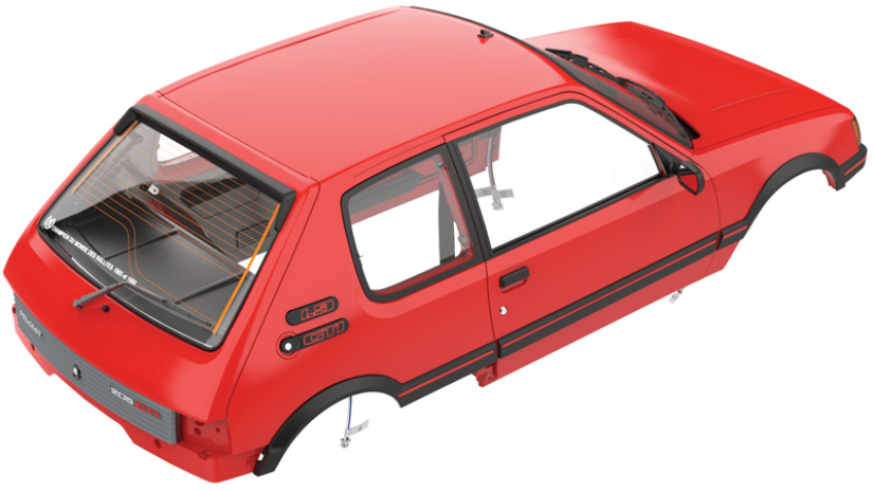
Rear lights with LEDs are installed on Bodywork .
Assembly drawings

General view