English
 français
 Deutsch
 español
 italiano
 português


Box 9
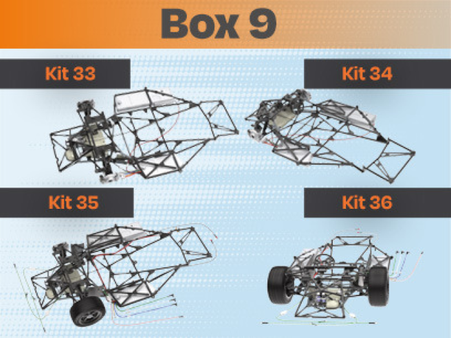
Kit 33
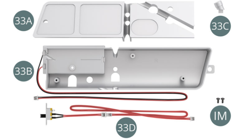
Parts of kit
- 33A Top Panel
- 33B Right fuel tank
- 33C Filling neck
- 33D Switch cable (double red)
- IM Screw M 1.7x 3.5 mm (x 2)
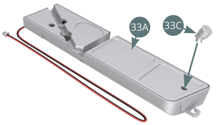
STEP 1
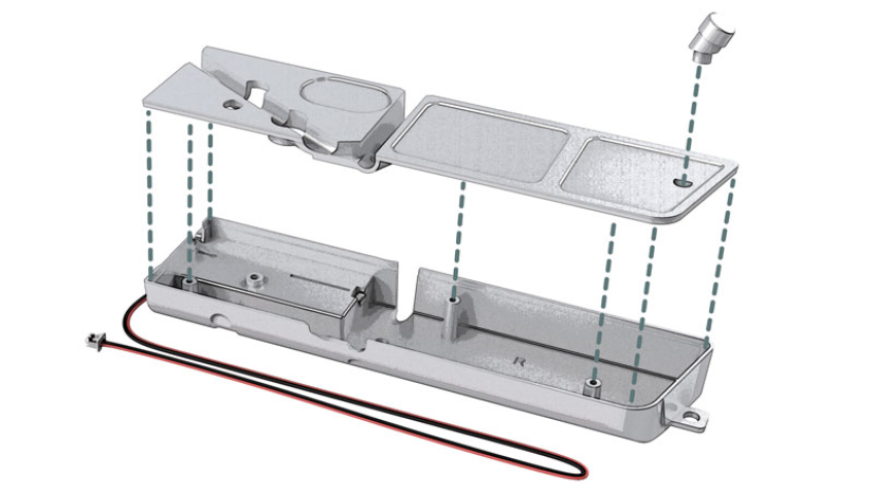
Position the top panel (33A) on the right fuel tank (33B) using the three pins (red arrows).
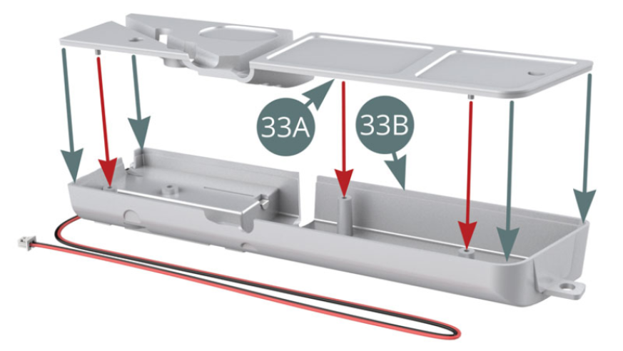
Position the filling neck (33C) on the top panel (33A) of the right fuel tank
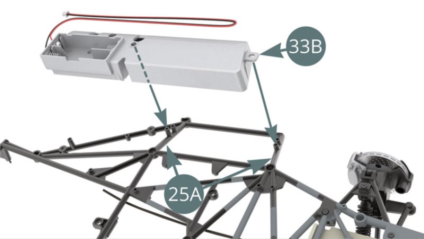
STEP 2
Position the right fuel tank (33B) on the lugs provided on the lower frame (25A) and secure with an IM screw (see illustrations). Route the red and black cable (33B) to the side of the upper part of the lower frame (25A) - blue arrow.

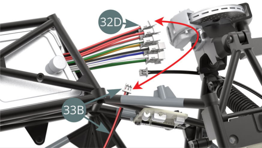
STEP 3
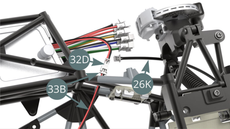
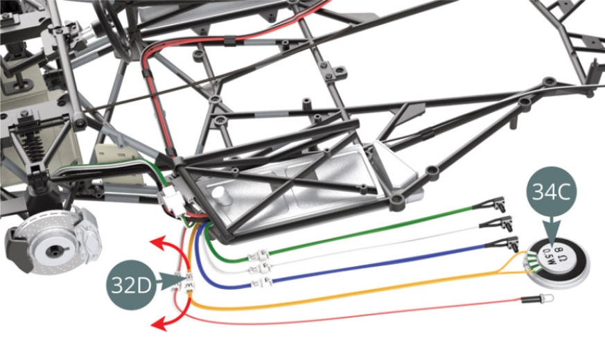
Connect the red and black cable (33B) - note its passage through the chassis tubes - to the socket of the red and black cable (32D) from the battery compartment (illustrations opposite).
STEP 4
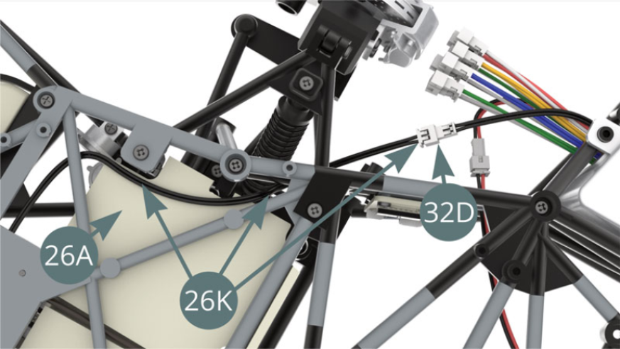
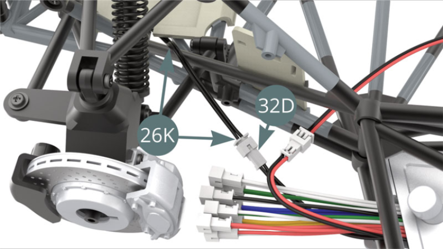
Guide the black double cable (26K) along the footrest (26A), then through the chassis tubes and plug it into the black twin cable socket of the battery compartment (32D) - illustrations opposite.
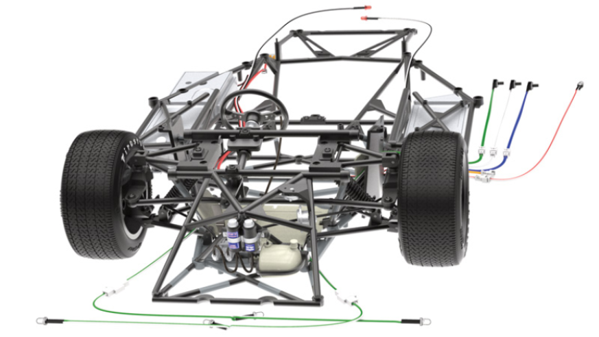
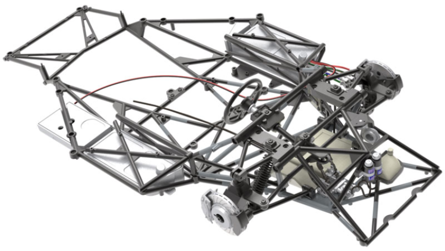
ASSEMBLY DIAGRAM
GENERAL VIEW
Kit 34
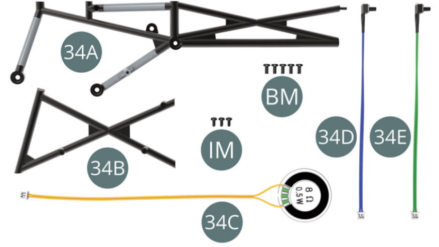
Parts of kit
- 34A Chassis
- 34B Chassis
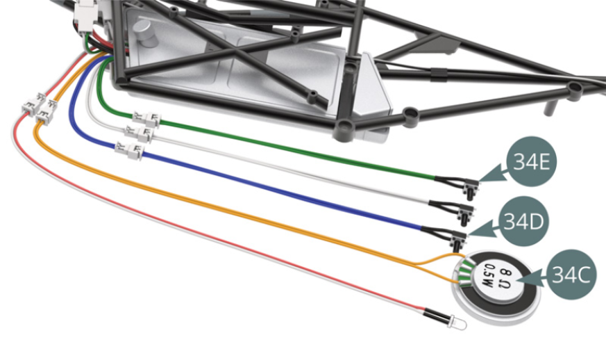
- 34C Speaker (yellow cable)
- 34D Engine Sound Switch (Blue Cable)
- 34E Horn Switch (Green Cable)
- BM Screw M 2.0 x 4 mm (x 5)
- IM Screw M 1.7 x 3.5 mm (x 3)
STEP 1
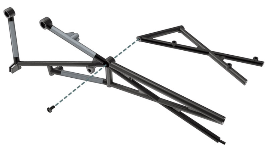
Assembly of the cockpit tubular mesh to the frame - Elements 34C, 34D and 34E will be used in future assemblies
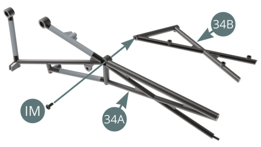
Pre-assembled 34A-34B chassis
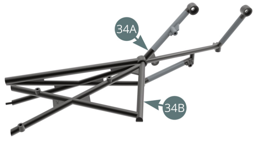
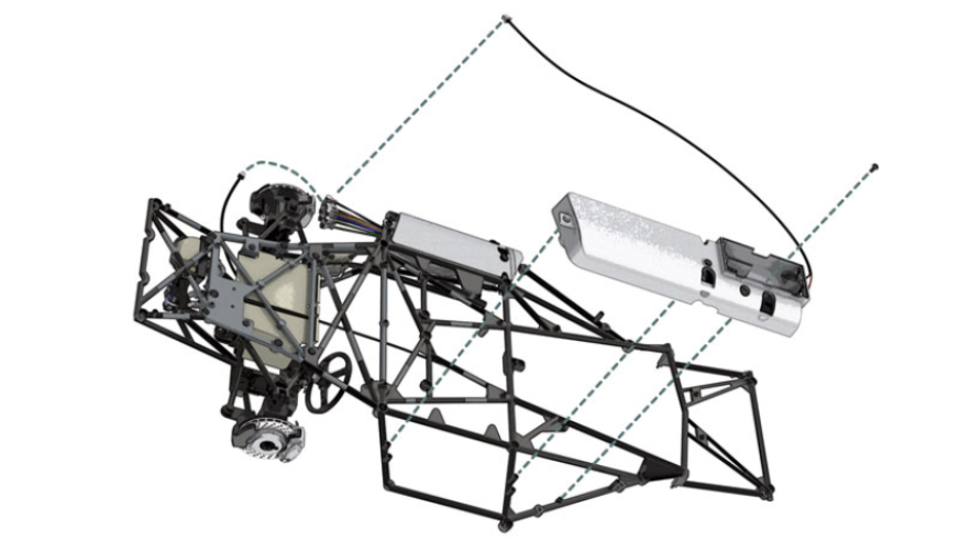
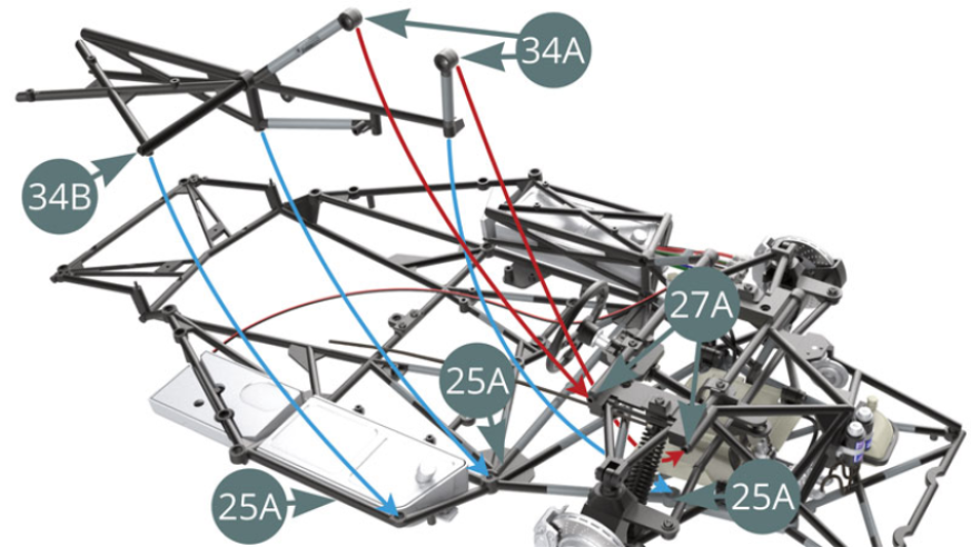
STEP 2
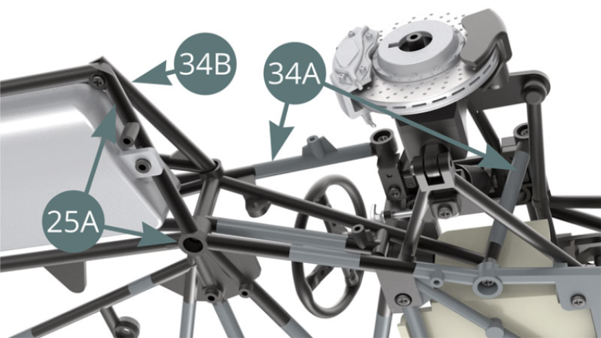
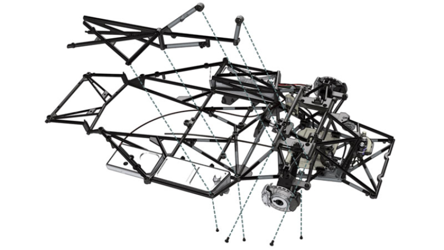
Position the pre-assembled chassis (34A-34B) - previous illustration - on the lower chassis (25A) and the dashboard frame (27A) - red and blue arrows. For a good understanding of the connection points, carefully study the following two illustrations
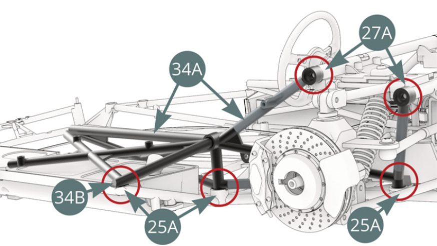
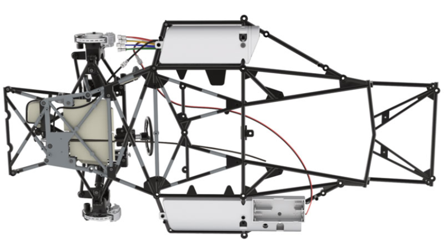
STEP 3
Identify the connection points (red circles) between the pre-assembled chassis (34A-34B) and the lower frame assembly (25A) / frame of the dashboard (27A). The fixation of these points must be ensured by the respective screws as indicated in the following three illustrations.
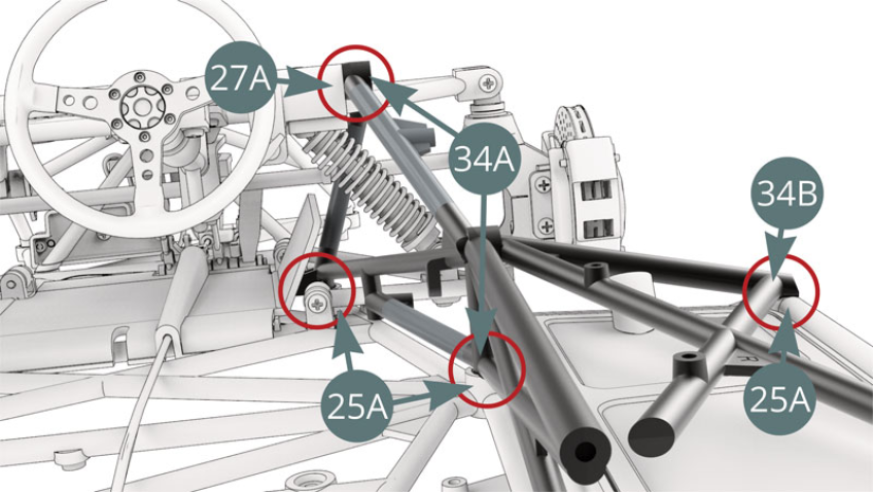
Attach the chassis (34A) to the dashboard frame (27A) with two BM screws.
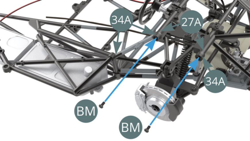
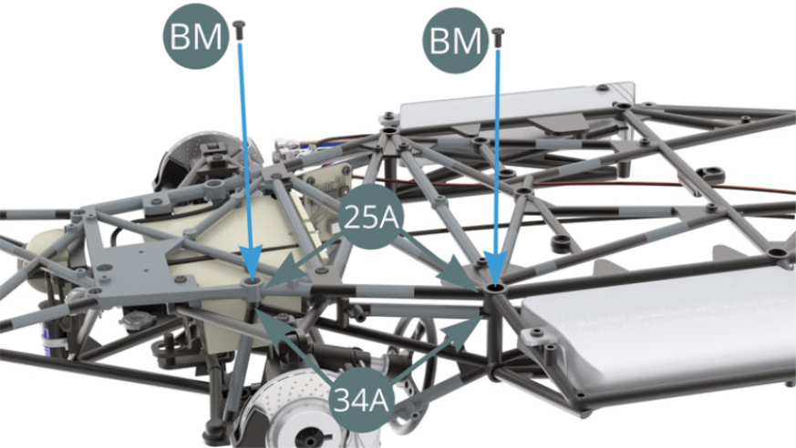
STEP 4
Attach the chassis (34A) to the lower frame (25A) with two BM screws
Attach the chassis (34B) to the lower frame (25A) with two IM screws.
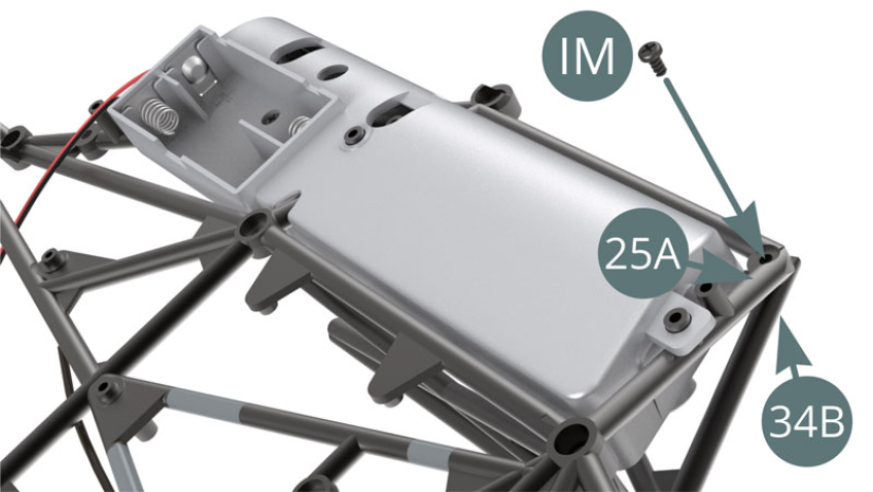
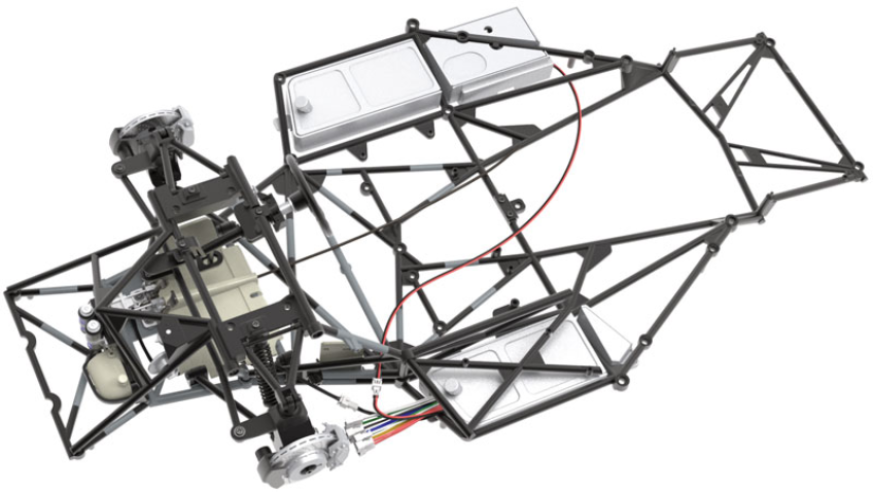
STEP 5
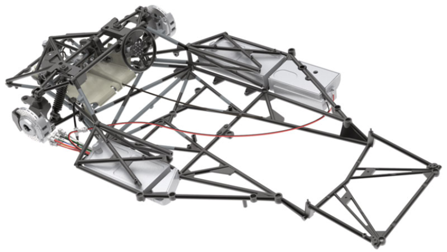
The assembly of the pre-assembled frame (34A-34B) on the lower frame (25A) is completed
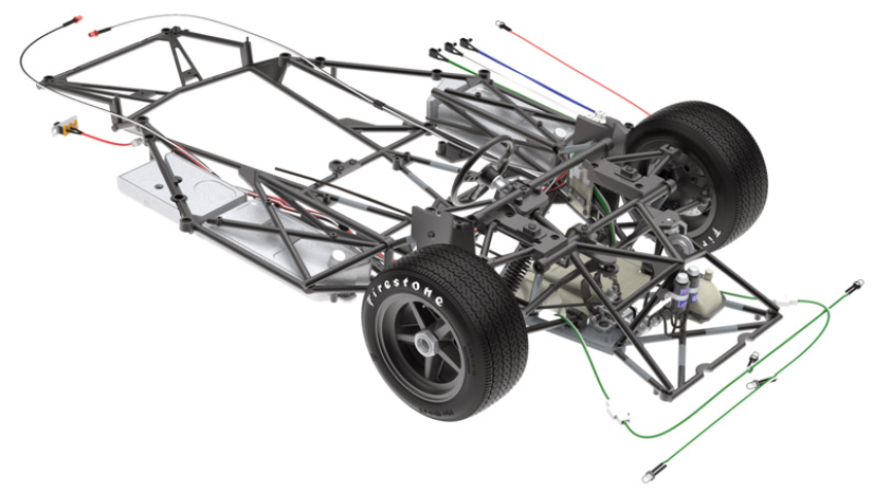
ASSEMBLY DIAGRAM
GENERAL VIEW
Kit 35
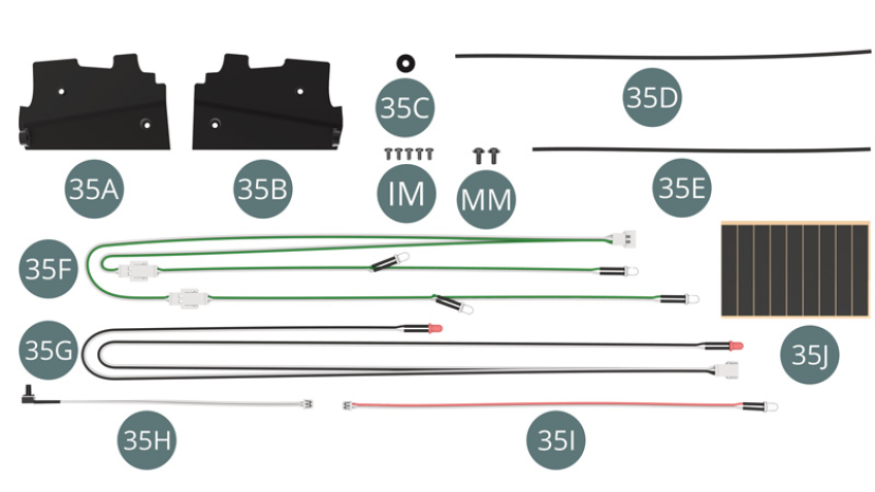
Parts of kit
- 35A Left mudguard
- 35B Right mudguard
- 35C Washer
- 35D Left brake hose
- 35E Right Brake Hose
- 35F LED Cable Headlight (White-Green)
- 35G LED Cable Taillights (Black-White)
- 35H Light switch cable (white)
- 35I Instrument Backlight LED Cable (Red-White)
- 35J Adhesive tape (x 6)
- IM Screw M 1.7 x 3.5 mm (x 5)
- MM Screw M 2 x 4 x 5mm (x 2)
STEP 1
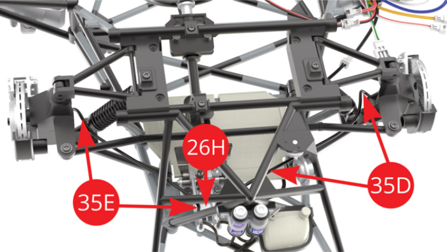
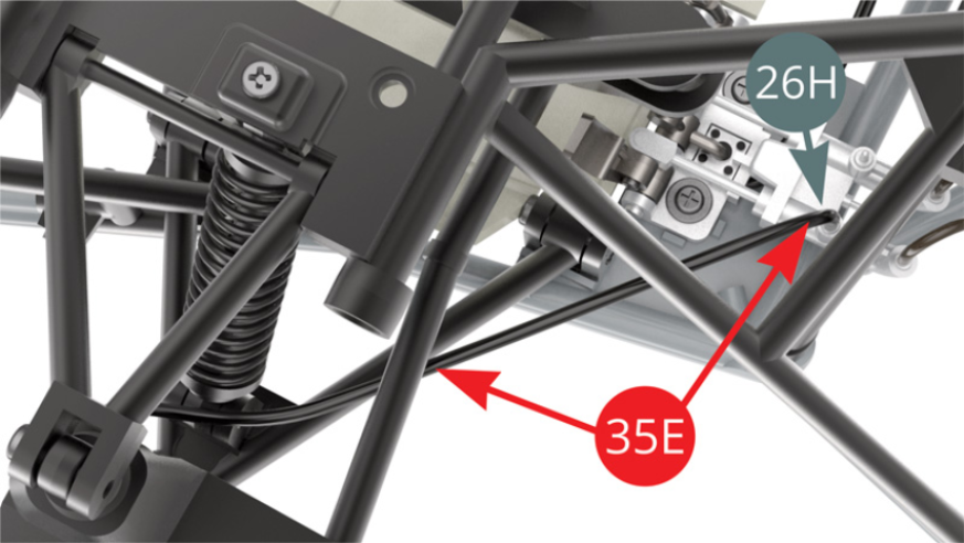
The illustration on the right shows the installation of the right (35E) and left (35D) brake hoses that will be carried out in the following four steps.
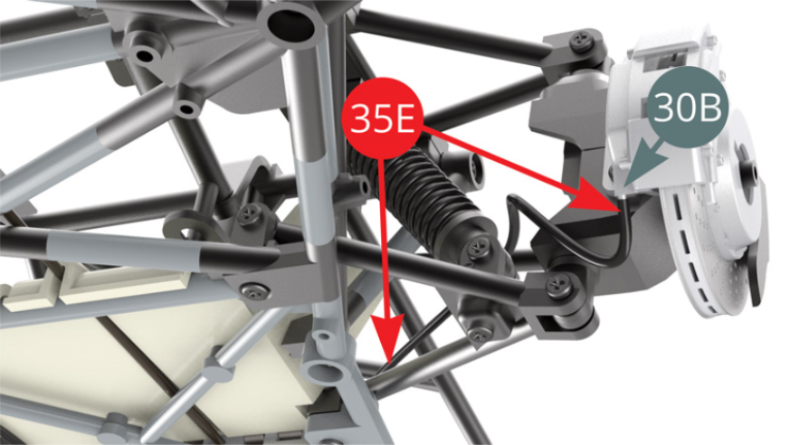
STEP 2
Position the right brake hose (35E) on the nipple located under the brake piston cover (30B). Guide the other end of the hose (35E) towards the master cylinder (26H) and attach it to the master cylinder (26H) - illustrations opposite.
STEP 3
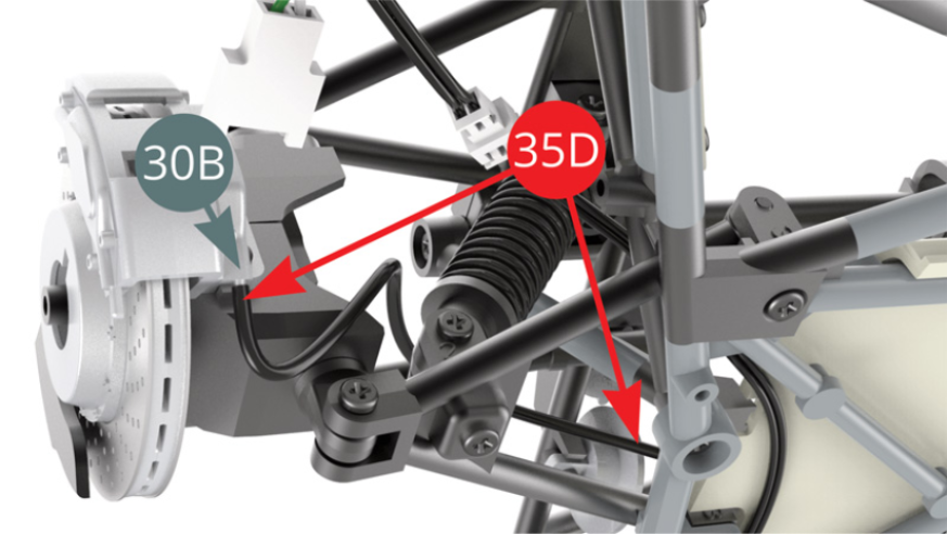
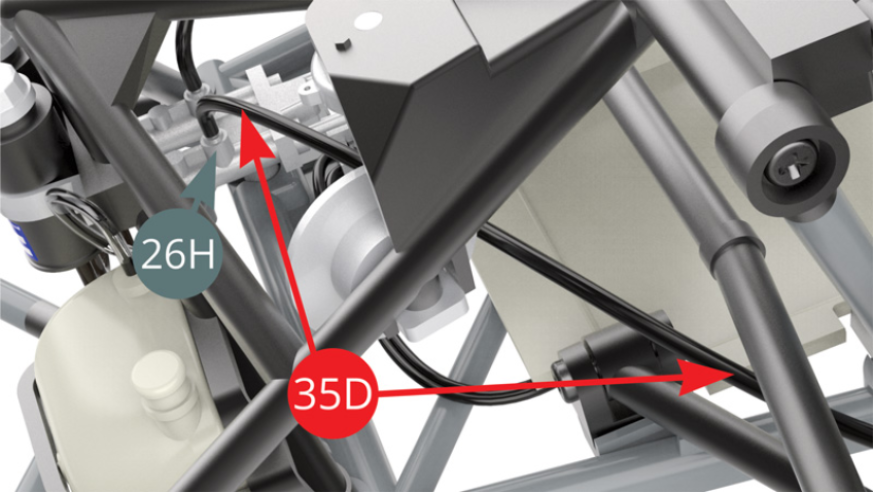
Position the left brake hose (35D) on the nipple located under the brake piston cover (30B). Guide the other end of the hose (35D) towards the master cylinder (26H and attach it to the master cylinder (26H) - illustrations opposite.
STEP 4
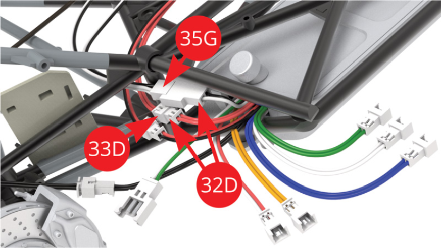
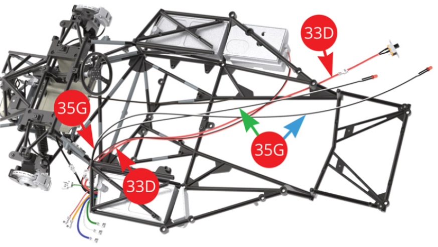
Connect the tail light LED cable / black-white (35G) and the switch cable / red (33D) to the same colour cables on the circuit board (32D).
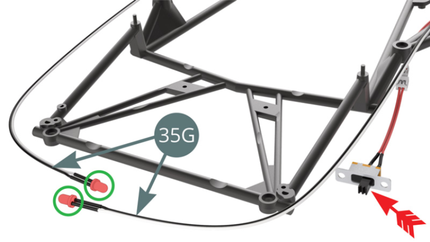
Carefully identify the longest (blue arrow) and shortest (green arrow) of the tail light LED cables / black-white (35G) in the illustration above.
STEP 5
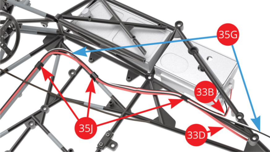
Guide the right fuel tank cable / black-red (33B), the switch cable / red (33D) and the longer (blue arrow) tail light LED cable / black-white (35G) along the right side of the frame, then tape them together on the main frame tube with two pieces of tape (35J). Guide the shorter tail light LED cable / black-white (35G) - green arrow - along the left side of the chassis, then tape it to the main frame tube with one piece of tape (35J).
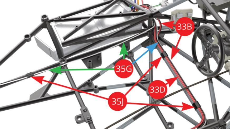
Attach the right fuel tank cable / black-red (33B), the switch cable / red (33D) and the longer (blue arrow) tail light LED cable / black-white (35G) to the right side of the frame with two more pieces of tape (35J).
STEP 6
The right fuel tank cable / black-red (33B), the switch cable / red (33D) and the tail light LED cable / black-white (35G) are installed on the chassis.
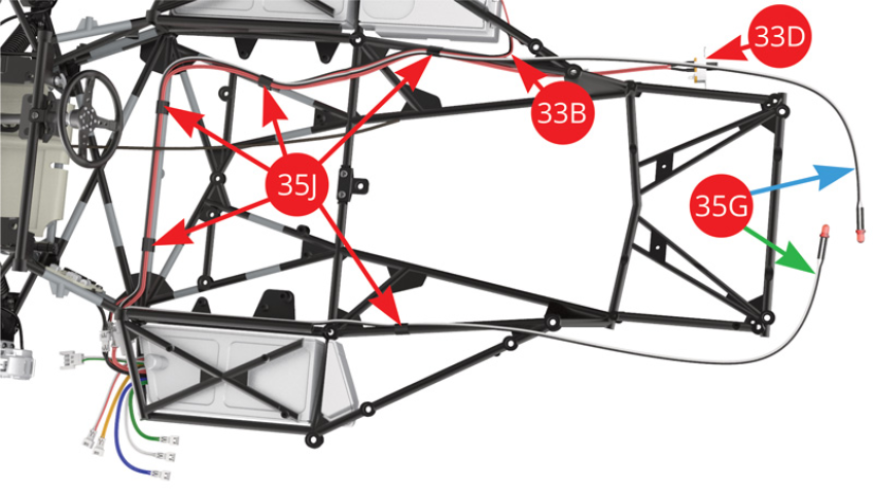
Connect the headlight LED cable / white-green (35F) and the cable of the same colour from the circuit board (32D). Identify the longest (blue arrow) and shortest (green arrow) of the headlight LED cables (35F), their positioning is specified in the detailed view in the next step.
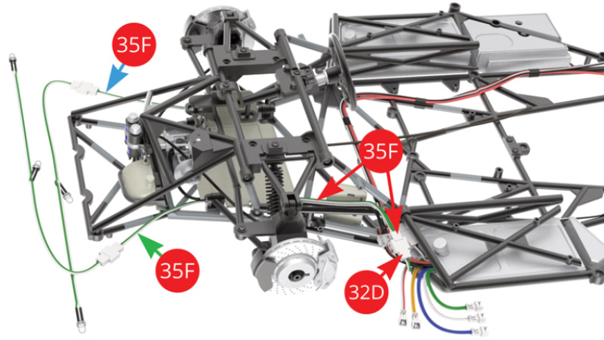
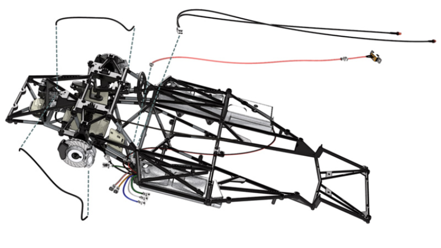
STEP 7
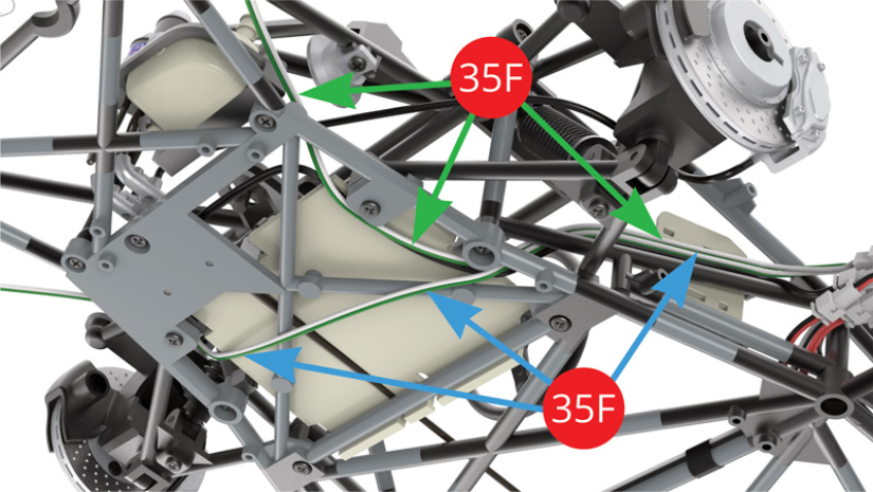
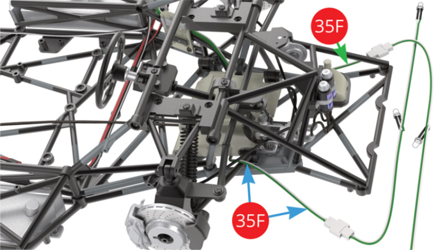
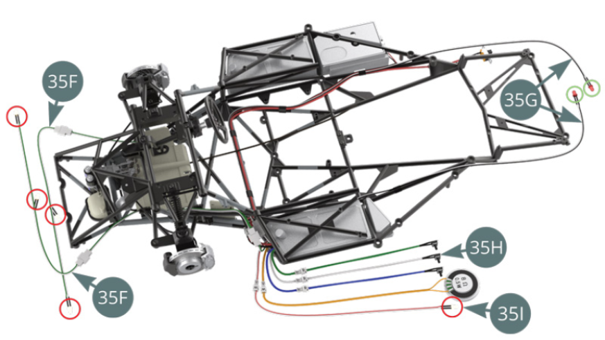
Identify the passage to the right of the longest (blue arrow) and to the left of the shorter (green arrow) of the headlight LED cables / white-green (35F) in the illustrations opposite.
STEP 8
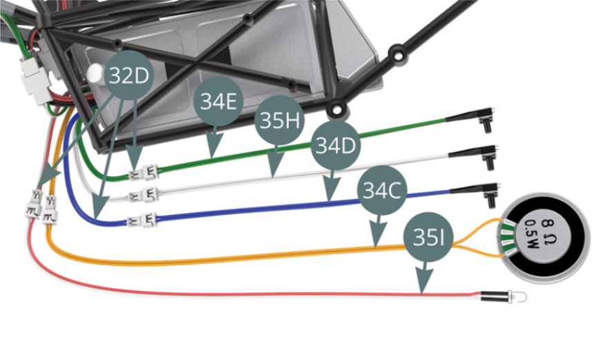
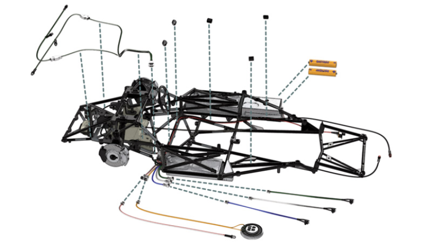
Connect the horn switch cable / green (34E), the light switch cable / white (35H), the engine sound switch cable / blue (34D), the speaker cable / yellow (34C) and the instrument light LED cable / red-white (35I) to the same coloured cables on the circuit board (32D).
Place two AAA batteries (not supplied) in the battery compartment / red arrows (33B). Turn switch 33D to the ‘on’ position (blue arrow).

STEP 9
Turn on the horn switch / green wire (34E) to hear it through the speaker (34C). Turn on the engine sound switch / blue wire (34D) to hear it through the speaker (34C).
Reduce the ambient light for better effect, then operate the lighting switch / white lead (35H) to observe the illumination of the headlight LEDs (35F), the instrument panel backlight LEDs / red circles (35I) illuminating in white and taillight LEDs / green circles (35G) glowing red.
STEP 10
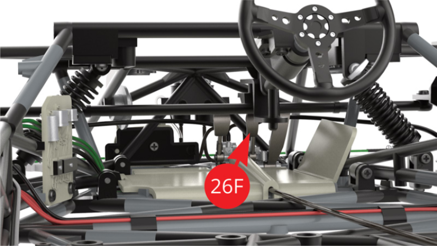
Press the middle pedal (26F) and observe the red lighting of the brakes on the tail light LEDs (35G) / illustrations opposite).
After having tested the operation of all the lights, turn the switch (33D) to the ‘off’ position (red arrow).
STEP 11
Disconnect the yellow speaker cable (34C) from the yellow circuit board cable (32D) so as not to damage it during the following assembly steps.
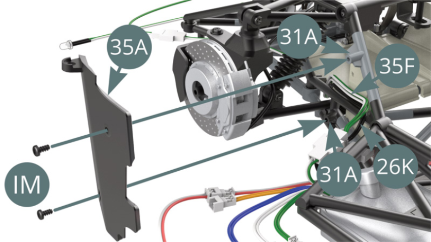
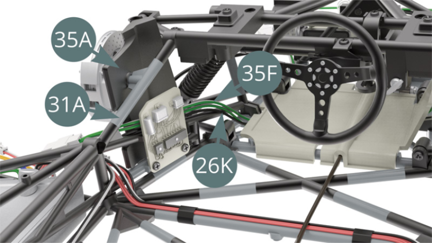
Position the left mudguard (35A) on the chassis (31A) - hidden behind the 35F and 26K cables - and secure it with two IM screws.
STEP 12
Check the correct positioning of the 35F (green-white) and 26K (black) cables after mounting the left mudguard (35A).
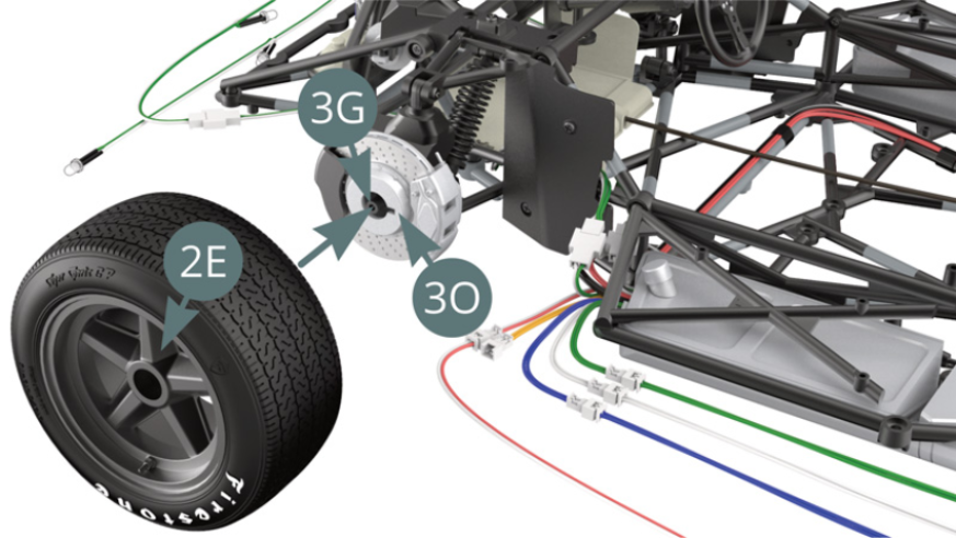
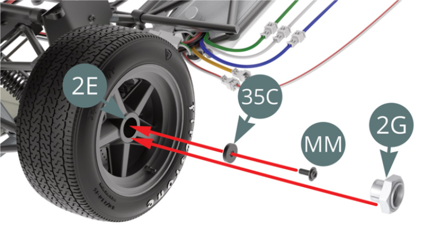
Position the left front wheel rim (2E) on the hub carrier axle (3G) by turning it gently until it engages in the notch on the outer brake disc (3O).
STEP 13
Attach the wheel rim (2E) with an MM screw by first passing it through the washer (35C). Position the hub cap (2G) on the wheel rim (2E).
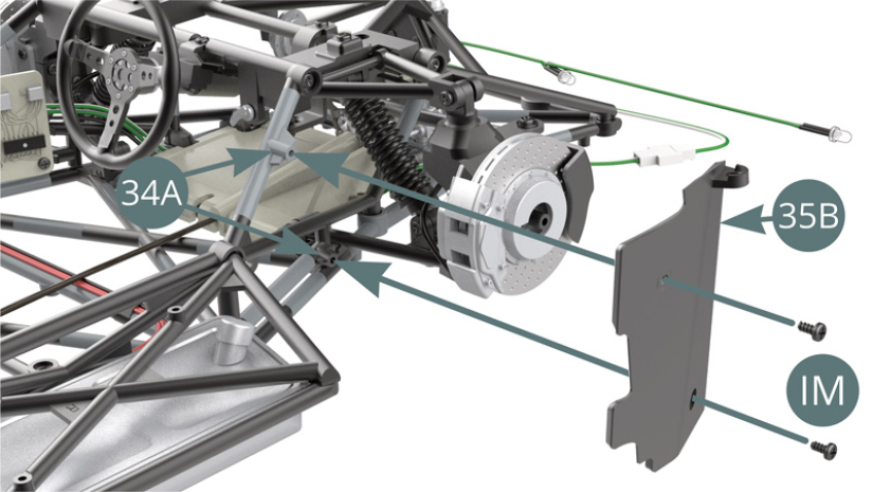
Position the right mudguard (35B) on the chassis (34A) and fix it with two screws IM.
ASSEMBLY DIAGRAM
GENERAL VIEW

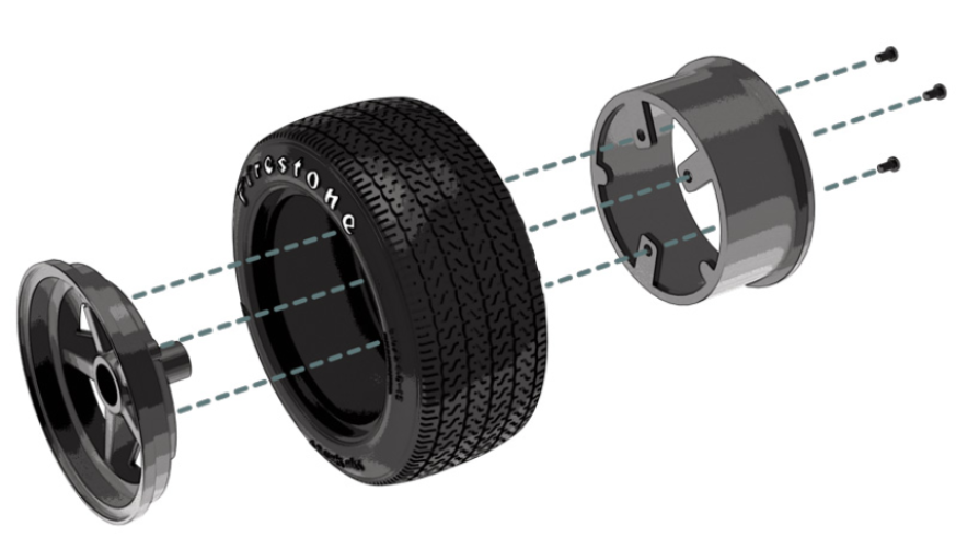
Kit 36
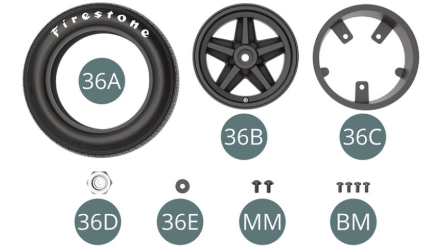
Parts of kit
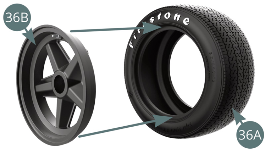
- 36A Front tyre
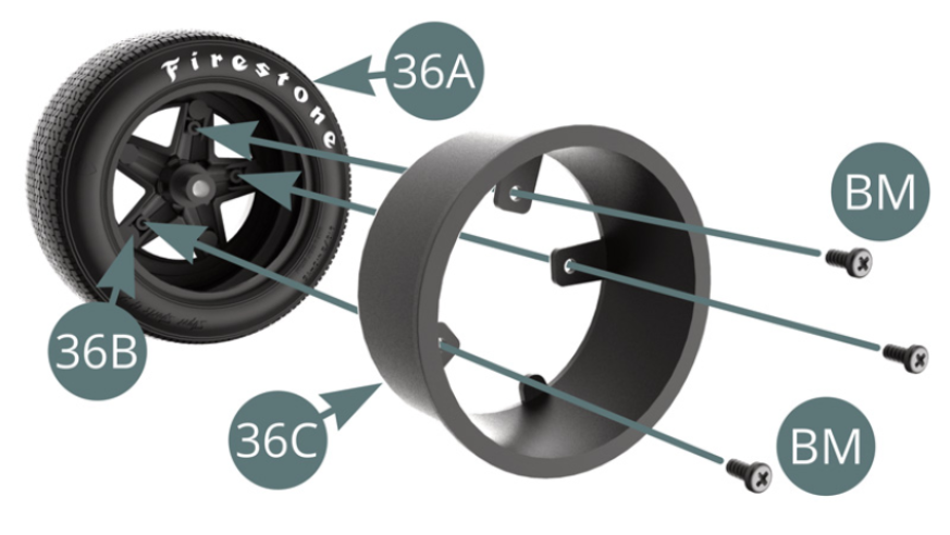
- 36B Front wheel outer rim
- 36C Front wheel inner rim
- 36D Hub Cover
- 36E Washer
- MM Screw M 2 x 5 x 5mm (x 2)
- BM Screw M 2 x 34 mm (x 4)
STEP 1
Position the outer rim (36B) on the front tyre (36A).
Position the inner rim (36C) on the front tyre (36A) and secure it to the outer rim (36B) with three BM screws.
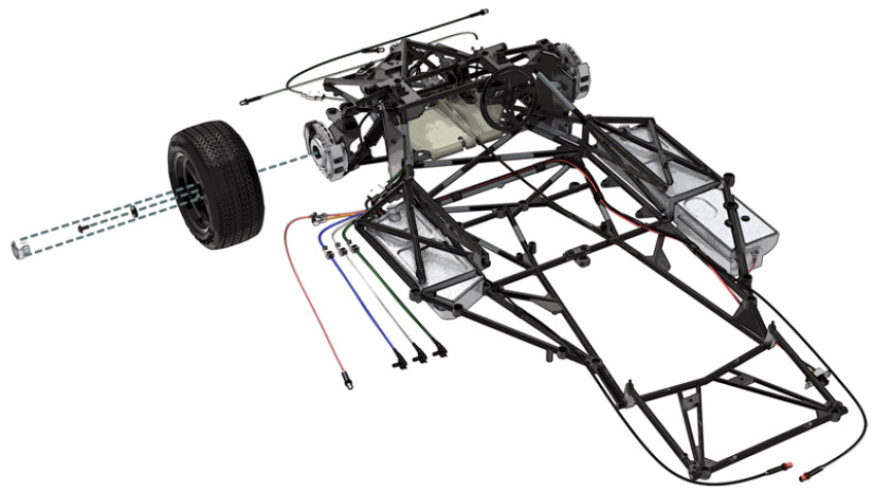
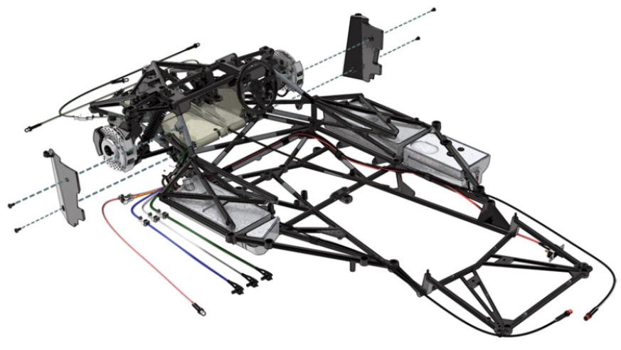
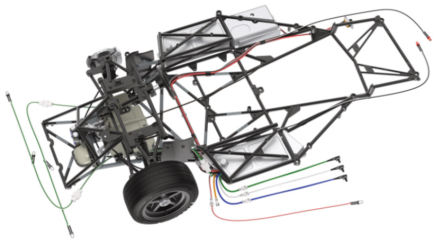
STEP 2
Position the rim of the left front wheel (36B) on the axle of the hub carrier (29H) by turning it gently until it engages the notch in the outer brake disc (30G).
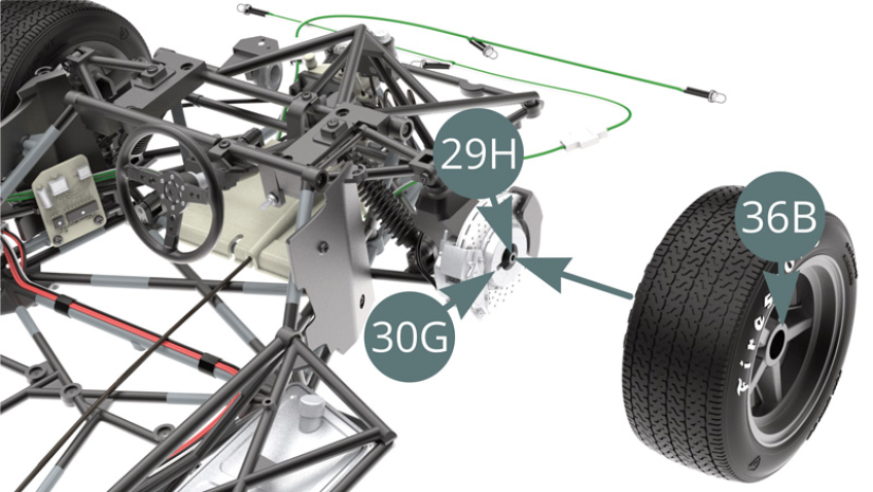
Attach the front outer wheel rim (36B) with an MM screw by first passing it through the washer (36E). Position the 36D hub cover (36D) on the wheel rim (36B).

ASSEMBLY DIAGRAM
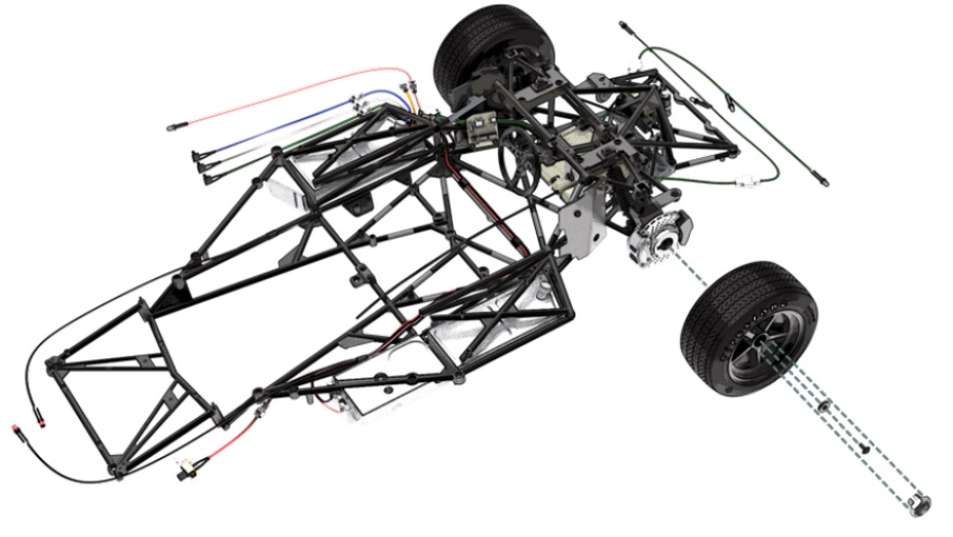
GENERAL VIEW