English
 français
 Deutsch
 español
 italiano
 português


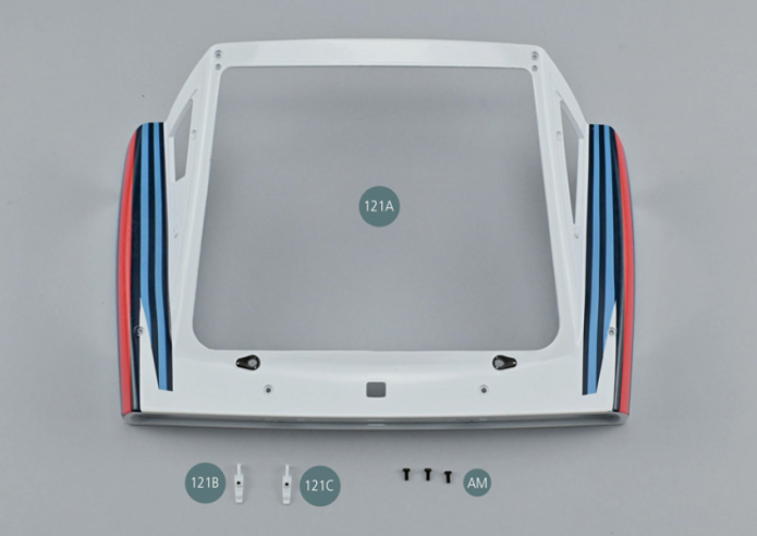
Box 31
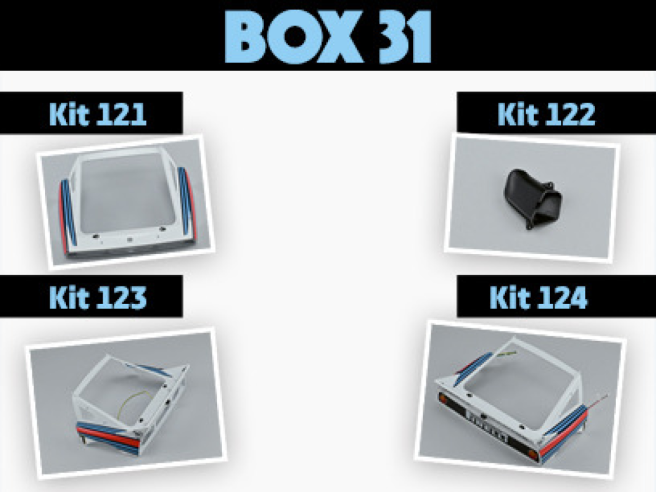
Parts of kit
- 121A Rear bonnet
- 121B Left hinge

Etape 1
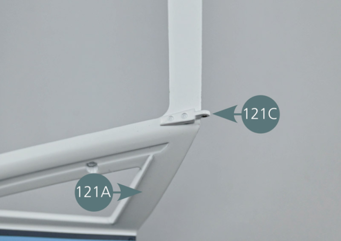
- 121C Right hinge
- Screw AM M 1.7 x 4 mm (x 3)
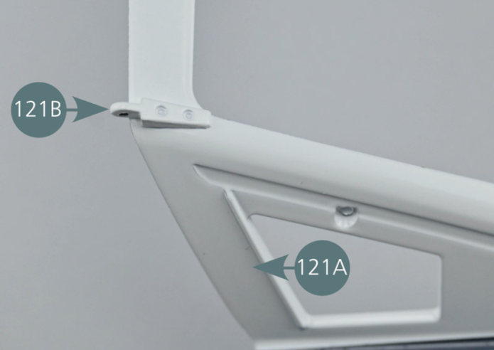
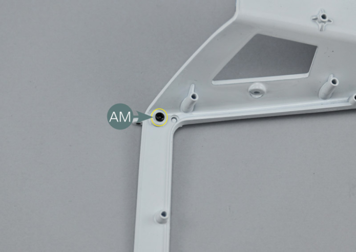
Positionner la charnière gauche 121B dans le siège supérieur gauche du capot arrière 121A. Retourner l’ensemble et fixer la charnière avec une vis AM.

Etape 2
Place the left-hand hinge (121B) in the left top recess of the rear bonnet (121A). Turn the assembly over and secure the hinge with an AM screw.

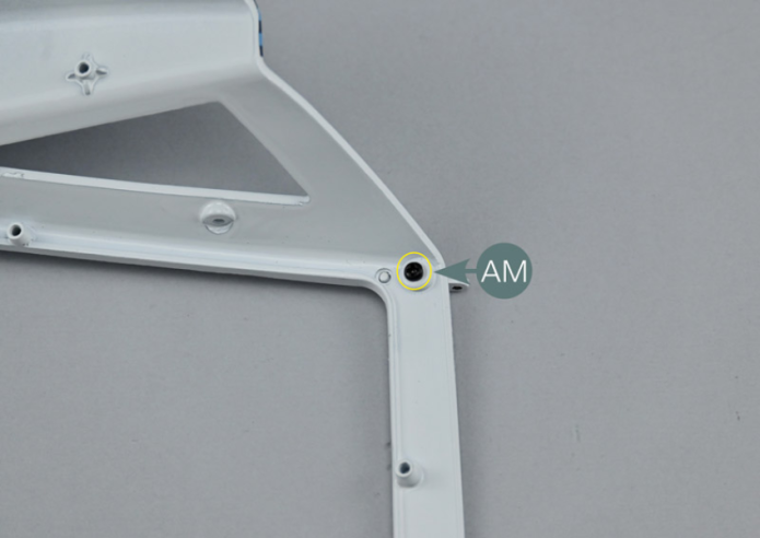
Positionner la charnière droite 121C dans le siège supérieur droit du capot arrière 121A. Retourner l’ensemble et fixer la charnière avec une vis AM.

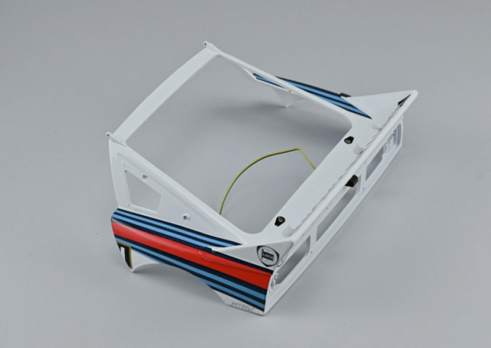
Vue générale
Position the right-hand hinge (121C) in the right top recess of the rear bonnet (121A). Turn the assembly over and secure the hinge with an AM screw.
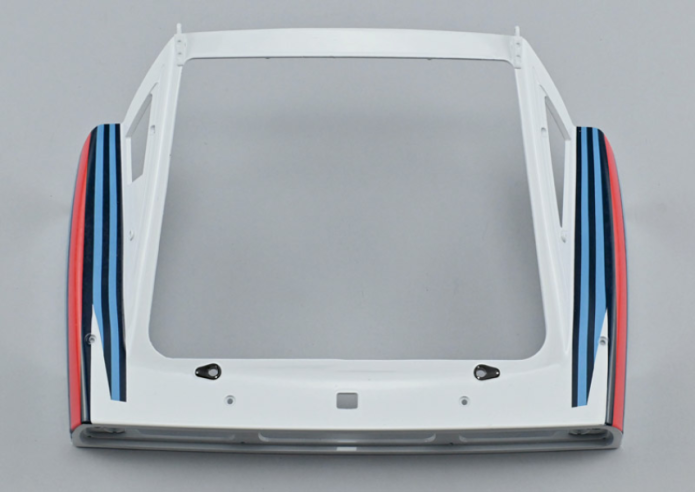
GENERAL VIEW
Parts of kit

Etape 1
- Screw AP P 1.7 x 4 mm (x 3)
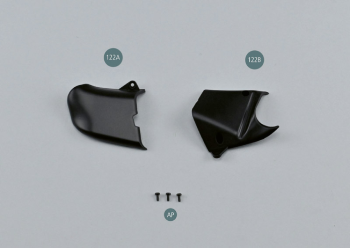
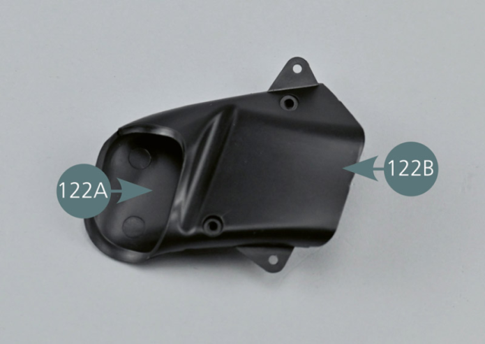
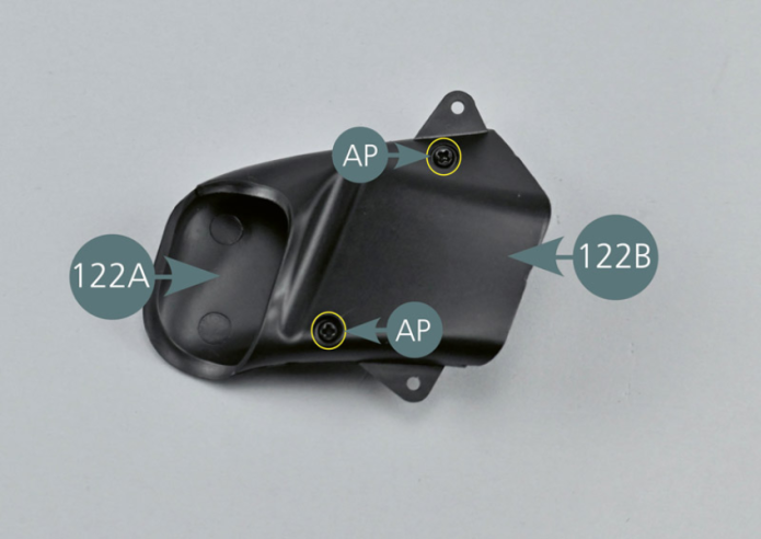
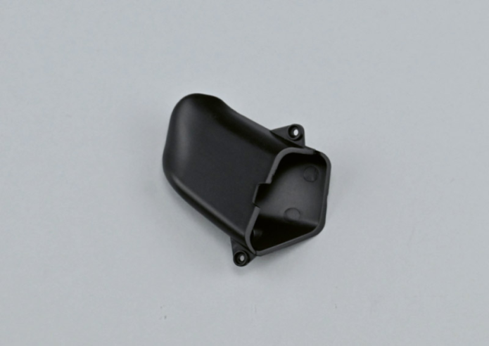
Assembler les deux éléments de l’écope d’air 122A et 122B en veillant à ce que les points de fixation soient positionnés dans les logements correspondants. Fixer l’ensemble avec deux vis AP.
Vue générale
Assemble the two parts of the air intake (122A&122B), ensuring that the mounting points are positioned in the corresponding housings. Secure the assembly with two AP screws.


GENERAL VIEW
Parts of kit
Etape 1
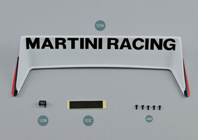
- 123C Adhesive tape
- Screw AM M 1.7 x 4 mm (x 5)
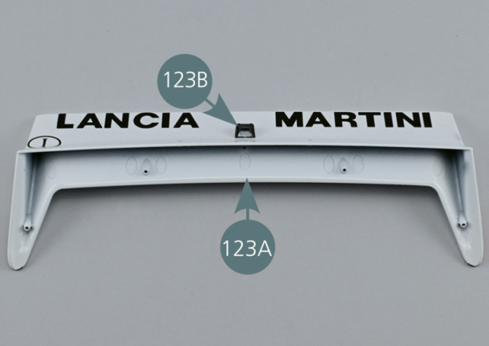
Retourner l’aileron arrière 123A comme indiqué sur la photo et insérer l’éclairage de la plaque d’immatriculation 123B avec la partie transparente vers l’extérieur.
Etape 2
Turn the rear spoiler (123A) as shown in the picture and insert the number plate light (123B) with the transparent part facing outwards.

Séparer le câble 19B (H1-1) de l’ensemble du câblage.
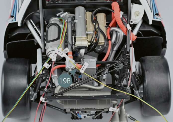
Separate the H1-1 cable (19B) from the rest of the wiring.


Etape 3
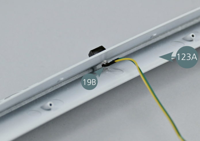
Plier les contacts de la LED à l’aide d’une pince et insérer le câble d’éclairage de la plaque 19B (H1-1) dans le logement prévu sous l’aileron arrière 123A. Fixer le câble avec le ruban adhésif 123C comme indiqué.
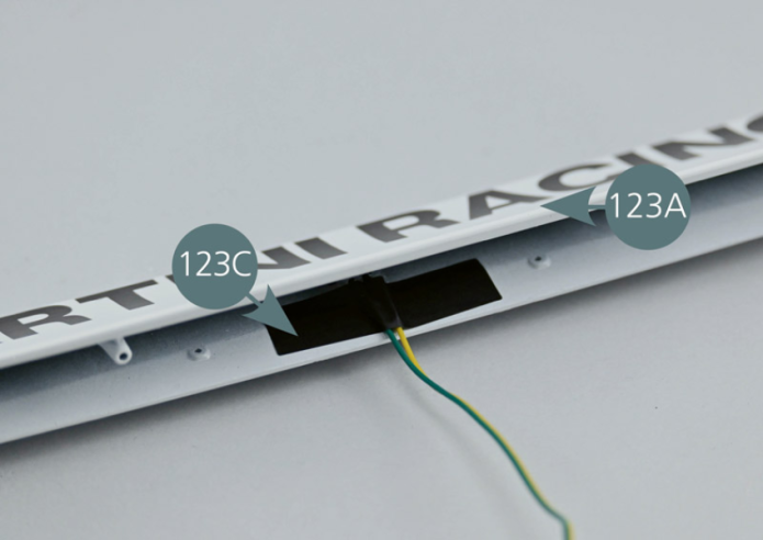
Bend the LED connections using pliers and insert the H1-1 cable lightning license plate (19B) into the housing provided beneath the rear spoiler (123A). Secure the cable with adhesive tape (123C) as shown.
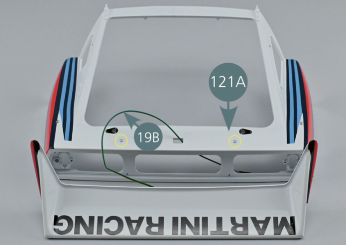
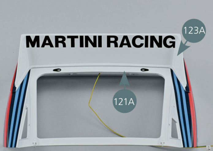
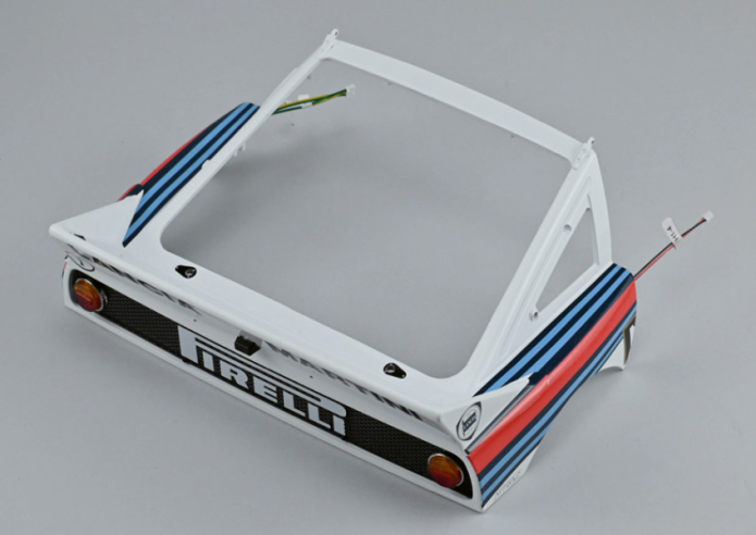
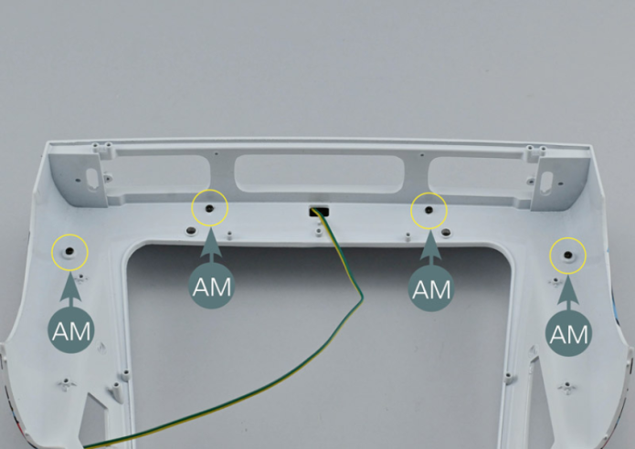
Pass the cable (19B) through the central rectangular opening in the rear bonnet (121A), working from the outside inwards. Position the rear spoiler (123A) on the rear bonnet (121A), aligning the mounting points with the corresponding openings (yellow circles). Turn the assembly over and secure the spoiler with four AM screws.
Vue générale


GENERAL VIEW
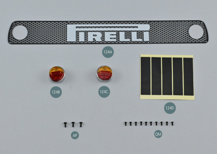
Parts of kit
Etape 1
- 124D Adhesive tape (x 5)
- Screw AP P 1.7 x 4 mm (x 3)
- Screw QM M 1.7 x 3 mm (x 8)
Positionner la grille arrière 124A sur le capot arrière 121A et la fixer avec huit vis QM (cercles jaunes).
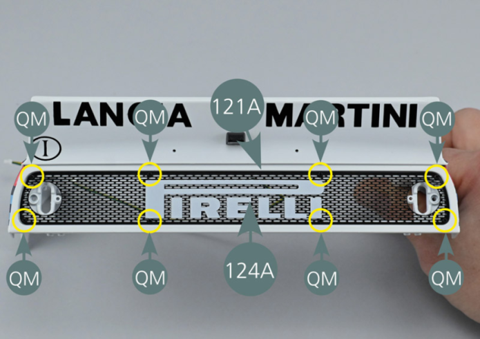
Etape 2
Position the rear grille (124A) on the rear bonnet (121A) and secure it with eight QM screws (yellow circles).

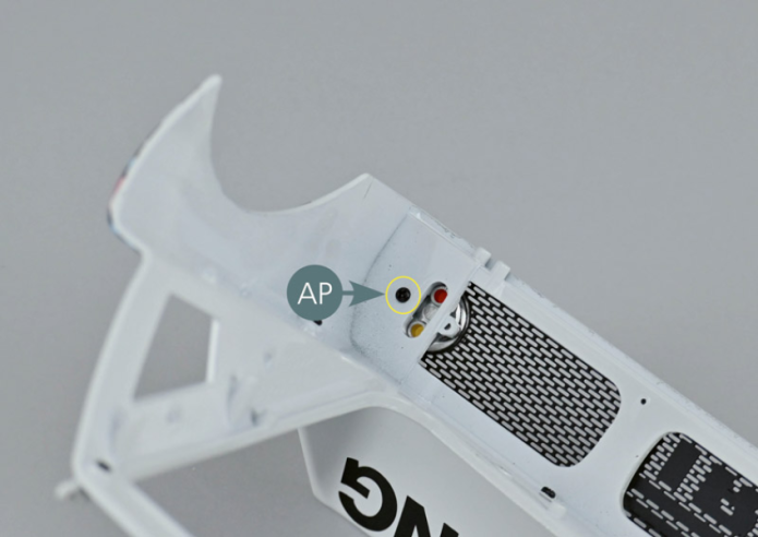
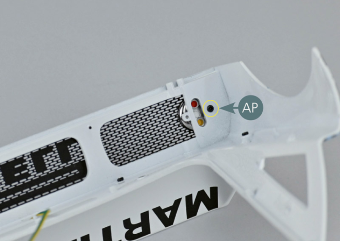
Positionner le feu arrière gauche dans le logement prévu sur la grille 124A et le capot arrière 121A, puis le fixer depuis l’intérieur avec une vis AP.
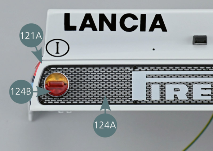

Etape 3
Place the left rear light in the housing located on the rear grille (124A) and the rear bonnet (121A), and secure it from the inside using an AP screw.

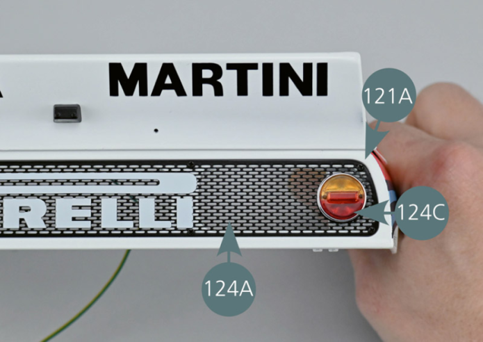
Positionner le feu arrière droit dans le logement prévu sur la grille 124A et le capot arrière 121A, puis le fixer depuis l’intérieur avec une vis AP.


Etape 4
Position the right rear light in the housing located on the grille (124A) and rear bonnet (121A), and secure it from the inside using an AP screw.
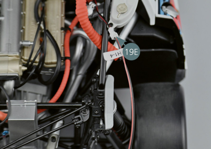
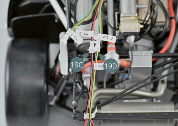
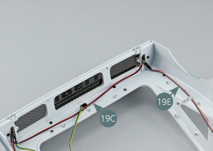
Déconnecter les câbles 19C (H1-2) et 19D (H1-3) du faisceau général sur le véhicule.Déconnecter également le câble 19E (H1-4).

Etape 5
Disconnect cables H1-2 (19C) and H1-3 (19D) from the vehicle wiring harness. Also disconnect cable H1-4 (19E).

Le câble 19C (H1-2) comprend deux LED. Insérer la première LED dans le trou supérieur (rouge) du feu arrière gauche. Insérer ensuite la seconde LED dans le trou supérieur (rouge) du feu arrière droit. Insérer la LED du câble 19D (H1-3) dans le trou inférieur (orange) du feu arrière gauche. Insérer la LED du câble 19E (H1-4) dans le trou inférieur (orange) du feu arrière droit.
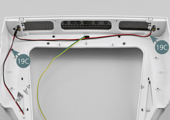
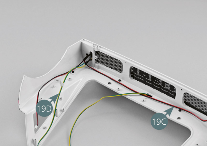
The H1-2 cable (19C) includes two LEDs. Insert the first LED into the top opening (red) of the left rear light. Then insert the second LED into the top opening (red) of the right rear light. Insert the LED from cable H1-3 (19D) into the lower opening (orange) of the left rear light. Insert the LED from cable H1-4 (19E) into the lower opening (orange) of the right rear light.
Etape 6


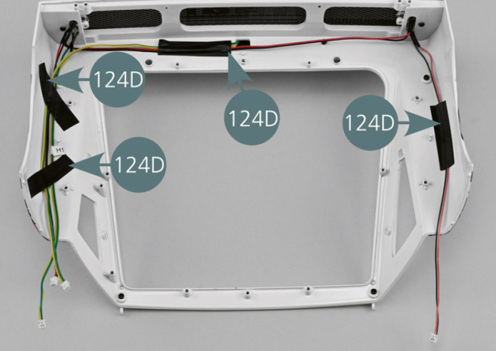
Fixer les câbles avec quatre morceaux de ruban adhésif 124D comme indiqué sur la photo.
Vue générale
Secure the cables with four strips of adhesive tape (124D) as illustrated.